Find more details on U.S. field telephone history on the U.S. Signal Corps Field Telephones Timeline.
A field telephone designated EE-8 was mentioned as early as 1922 in Primary Batteries. Training Pamphlet No. 7. [1]:
EE-8. Field telephone, to replace EE-3, EE-4 and EE-5 (development not completed).Apparently, the use of the BA-1 battery was still envisaged at that stage. The development of what eventually became the production EE-8 apparently continued for many more years. The EE-8 design was finalised in 1936, service-test units were procured from Automatic Electric in 1937, and following successful testing, the EE-8 was standardised for production in 1938 [11]. By the time the United States entered World War II in 1941, the Signal Corps had already ordered approximately 70,000 EE-8 telephones. U.S. production capacity subsequently increased from just 50 units per day to a whopping 2,000 per day [8], with production shared among eight manufacturers [11]:
The EE-8 also influenced the development of other field telephones, most notably the Swiss Army FTf 50 [21], and may have partly inspired the Norwegian TP-6N.
In terms of design and features, the EE-8 [6] was a clear successor to the EE-3/EE-4/EE-5 family, but was lighter, more robust, and used a more practical battery arrangement (two 1.5 V BA-30 cells instead of the 3 V BA-1). The original EE-8 [2] was followed by the EE-8-A [3], featuring a different capacitor arrangement and handset, and subsequently by the EE-8-B [5], which introduced a more efficient magneto and replaced the aluminium chassis with a steel one. After World War II, EE-8 telephones were refurbished and continued in service in numerous countries across Europe and elsewhere. Licensed production also took place in at least Italy [12] and Germany [10]. In the United States, the EE-8 was still mentioned in the 1956 edition of Field Wire Techniques, FM 24-20 [7], but was absent from the 1960 edition [9], by which time it had been superseded by the next-generation TA-43/PT. The EE-8 also formed the basis of the EE-105 lineman's telephone, which incorporated an additional filter unit for connecting to carrier telephone lines and a 1,000 Hz whistle for signalling to a carrier terminal [13].
The handset TS-9-(*) existed in a remarkable number of variants (TM 11-333 [6] lists 23), apparently reflecting differences between manufacturers. All variants are electrically equivalent [14], although individual components, such as the transmitter and receiver caps and elements, are not necessarily interchangeable between models. The push-to-talk function is operated by a butterfly-style rotary switch. The TS-9 handset was also used with other Signal Corps equipment. Wisdomwingsandwar provides a useful photographic comparison of several TS-9 variants. Usarmydatadepot (offline but preserved on archive.org) shows the only to me known image of a TS-9-A used with the original EE-8.
Description of telephones EE-8, EE-8-A and EE-8-B: (From TM11-333 [6], abridged)
Telephone EE-8-(*) is a portable field telephone designed for use on either local or common battery telephone systems. It is compact, rugged, and portable, and in performance equals the best present day commercial telephones. It contains all the elements necessary for a combination local battery and common battery telephone, and the circuit elements are arranged for antisidetone transmission. When Telephone EE-8-(*) is used as a local battery telephone, talking range of 1 to 17 miles may be expected on Wire W-110-B, depending on weather conditions and the type of construction of the wire line. A rectangular portion of the leather has been cut out of the cover of Telephone EE-8 and replaced by a more flexible material. This permits the handset to depress the lever switch when it is hung on the outside of the case. Otherwise, Telephone EE-8 is externally similar to Telephones EE-8-A and EE-8-B. The case containing Telephone EE-8-(*) is made of leather or canvas and has an adjustable carrying strap. The cover is hinged at the back, overlaps the sides and front, and fastens in front with a snap fastener. The space within the case not occupied by the body is used for storing the handset. All elements of Telephones EE-8 and EE-8-A are mounted on an aluminum alloy chassis. The elements of Telephone EE-8-B are mounted on a sheet steel chassis. The battery compartment is on the upper left side of the body. The chassis is fastened to the case by seven machine screws. The terminal block forms the top of the body. On it are mounted the following: (a) The lever switch on the left edge above the battery compartment. (b) The screw switch to the right to the lever switch, marked with an arrow pointing clockwise to CB and counterclockwise to LB. (c) The jack, which is a three-contact jack suitable for accommodating Plug PL-58. This jack is assembled with three terminals for the handset cord, marked T & BAT +, C, and REC. Four studs are provided for separating the conductors of the cord connected to the terminals, and a screw eye is provided for fastening the stay cord of the handset cord. (d) Two line binding posts, marked L1 and L2. (e) One binding post, marked BAT-. Handset TS-9-(*) includes the following: (1) Cord CC-333, which is a rubber-covered cord containing three rubber-covered conductors colored black, red, and white. These conductors at one end of the cord are connected to the terminals on the jack marked T & BAT +, C, and REC, respectively. The conductors at the other end of the cord are connected to terminals marked BK (or B), R, and W of the handset respectively. Stay cords are fastened at both ends. (2) The handle, which contains suitable terminals, connections between the parts of the handset, and the handset switch in the transmitter circuit. (3) A receiver element or unit in one end of the handle and a transmitter element or unit in the other end.
A screw-operated selector allows switching between local-battery (LB) and central-battery (CB) operation. For CB operation, a hook-switch lever provides a resting position for the handset (could be operated with closed lid on the original EE-8 with insert in lid). Additional features include binding posts for an external battery and separate handset terminals alongside the handset plug.
| Part | EE-8 (1936) | EE-8-A (1942) | EE-8-B (1944) |
|---|---|---|---|
| Carrying case | Leather, with insert in lid | Leather or canvas | Leather or canvas |
| Chassis | Aluminium | Aluminium | Steel |
| Capacitors | Separate | Combined | Combined |
| Magneto | GN-38 | GN-38 | GN-38-A, GN-38-B |
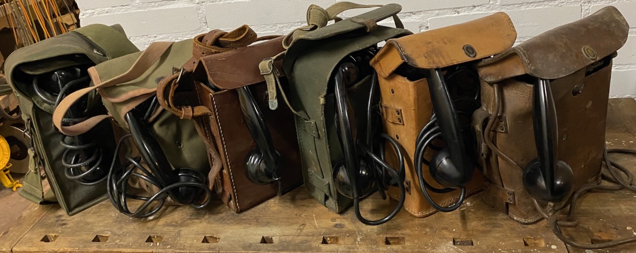
A collection of different EE-8-() (from left to right): German, Italian, French refurb. with French Handset, EE-8-B Canvas, EE-8-B Leather, EE-8-A Leather.
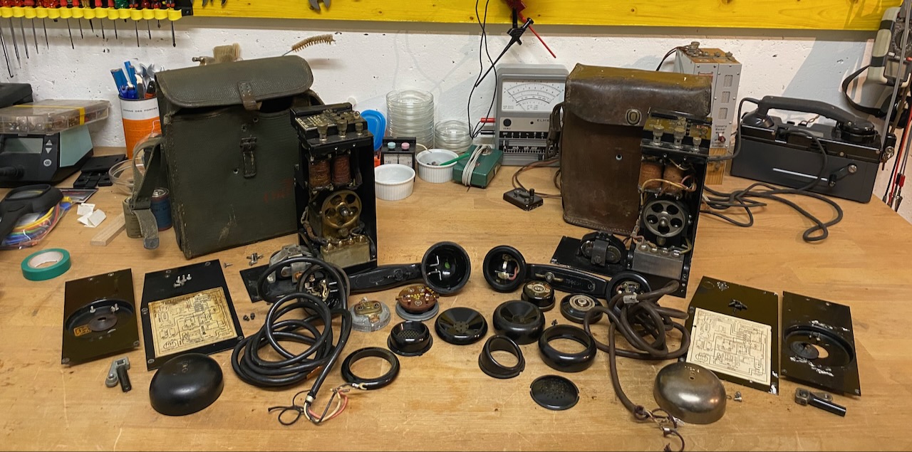
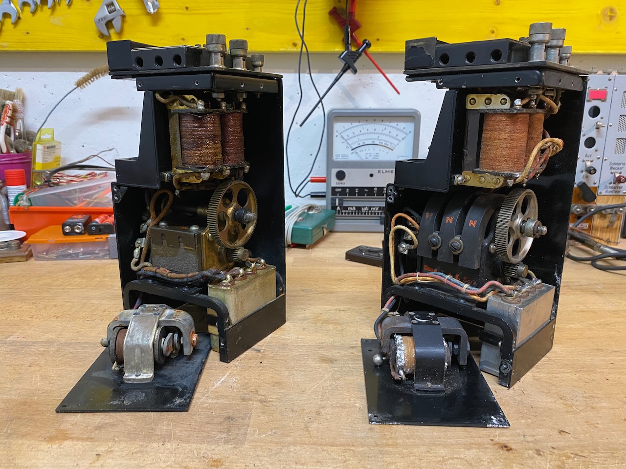
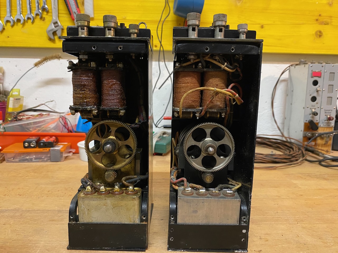
Disassembled EE-8-B (Automatic Electric, Kellogg Handset) and EE-8-A (Connecticut Telephone & Electric Company).
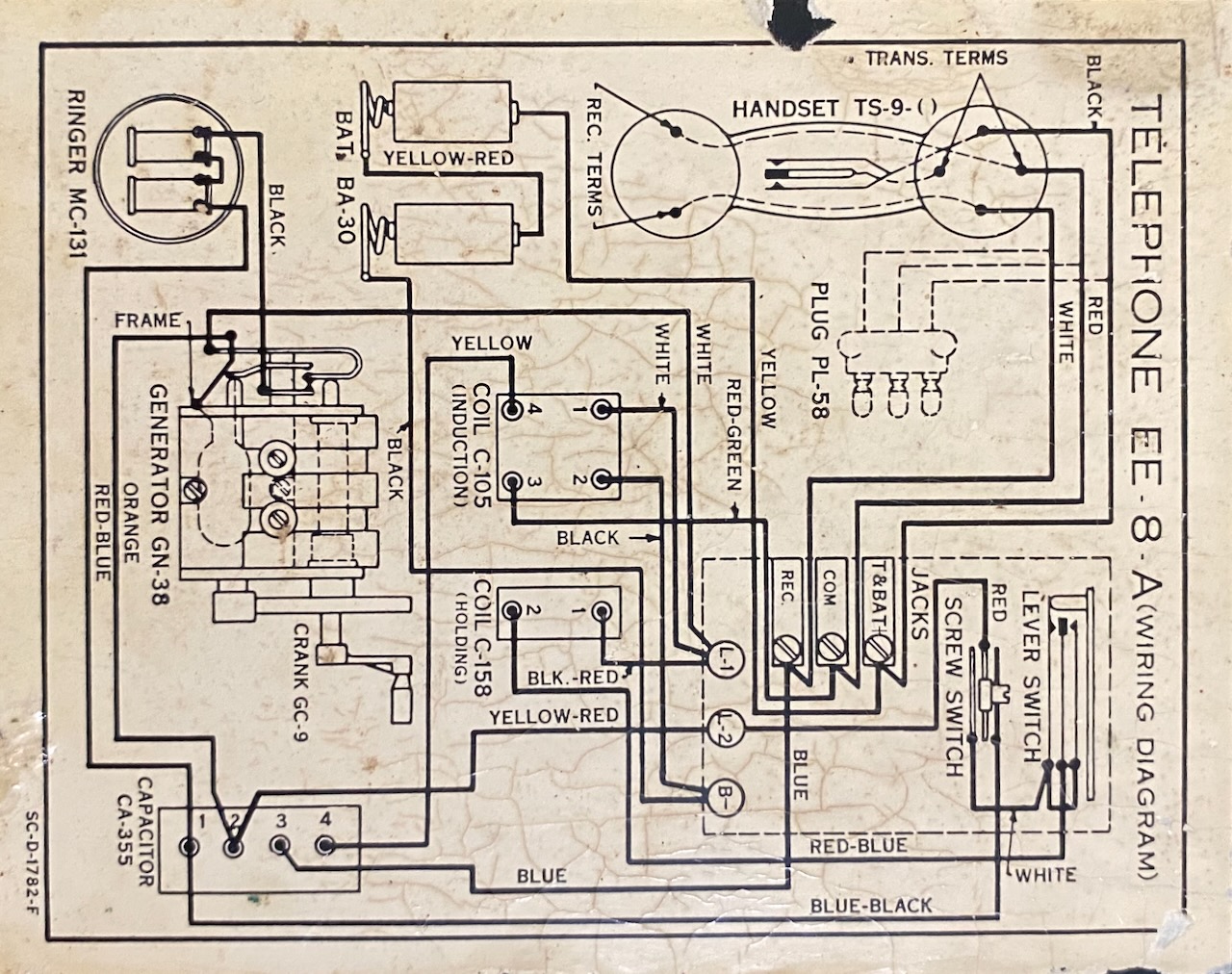
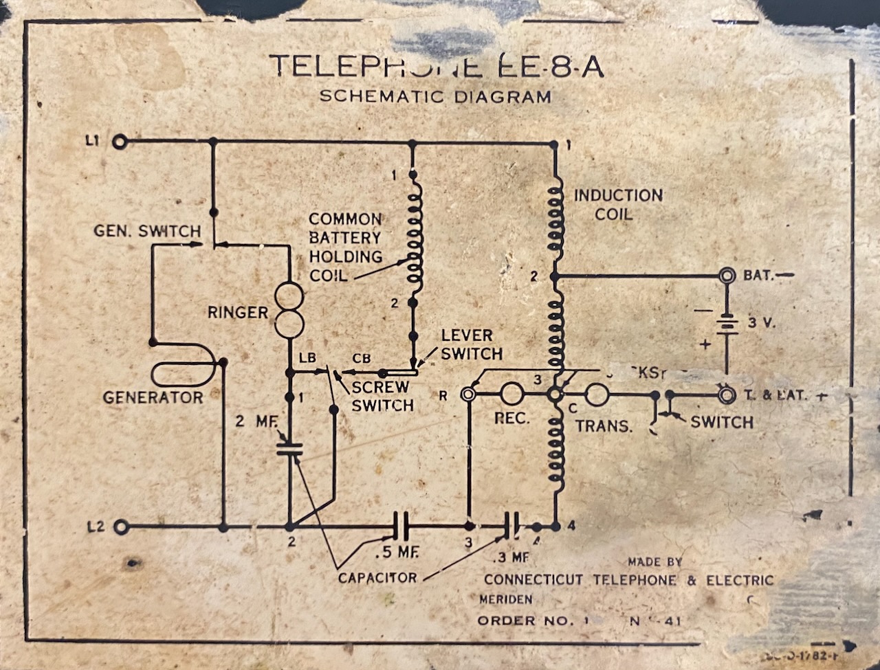
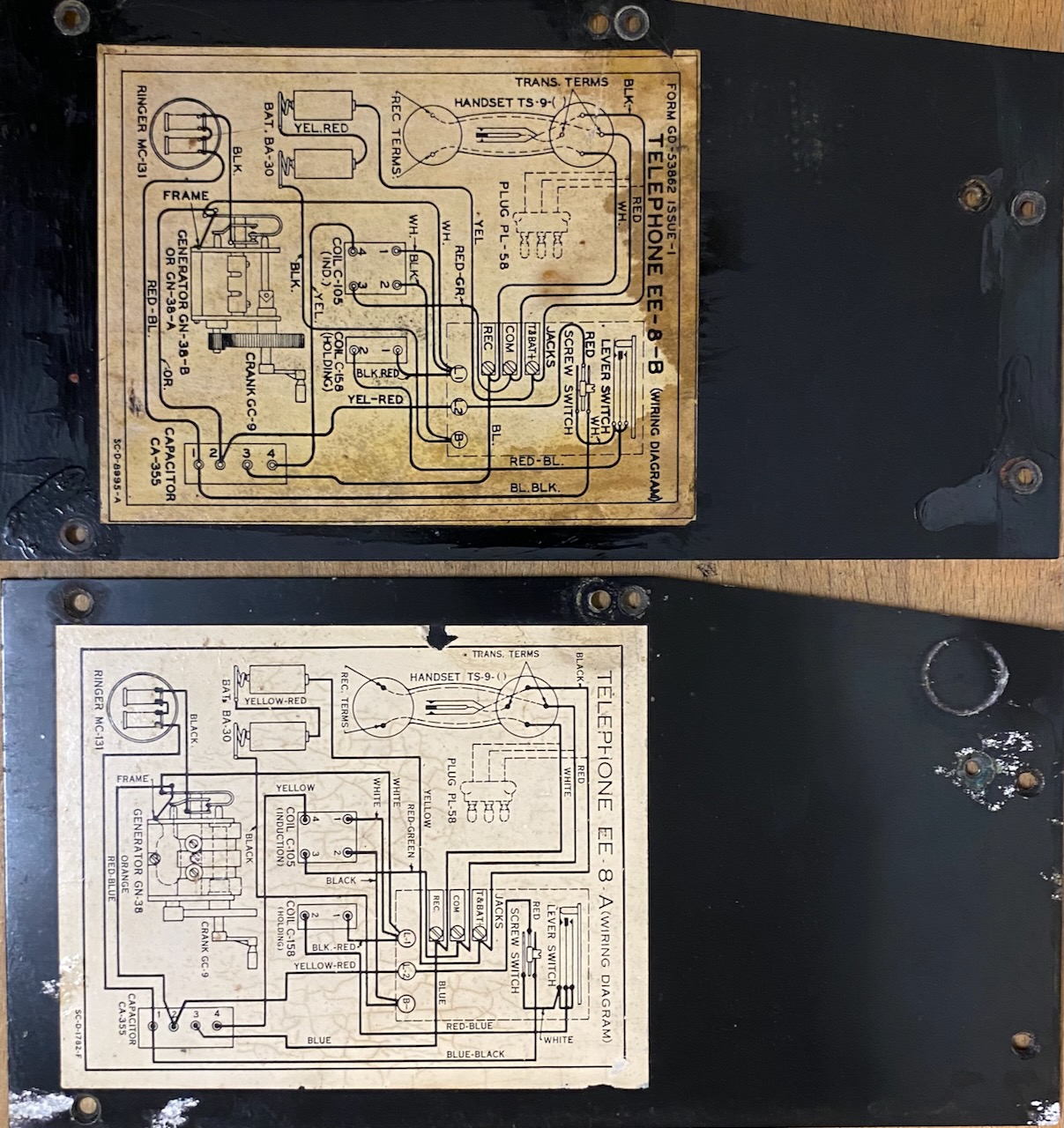
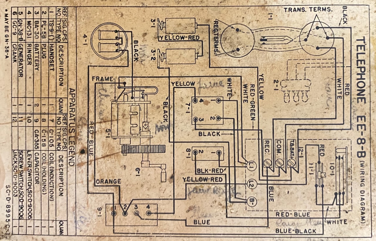
Wiring Diagram EE-8-A.
Generator GN-38.
SC-D-1782-F (Signal corps diagram 1782, the F maybe indicates the version of the diagram)
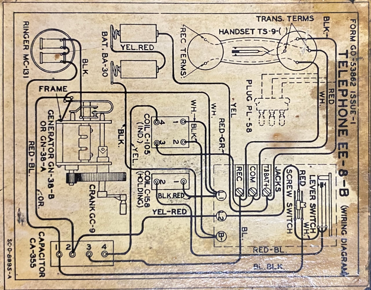
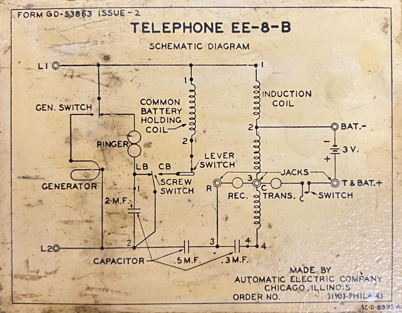
Wiring Diagram EE-8-B.
Generator GN-38-B or -A.
SC-D-8995-A (Signal corps diagram 8995, the A maybe indicates the version of the diagram)
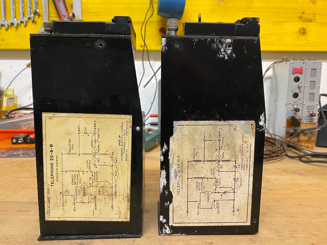
Circuit diagram EE-8-A.
Circuit diagram EE-8-B.
Open chassis, left -B, right -A.
Ringer MC-131 removed and bell removed.
Open chassis, left -B, right -A.
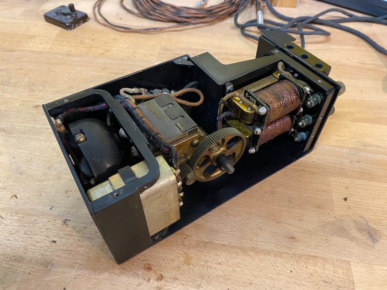
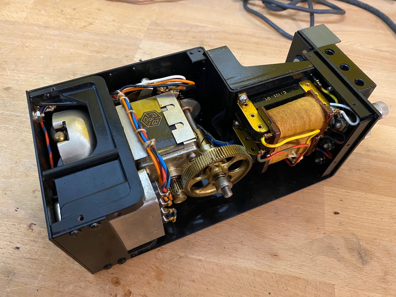
The left coil is the induction coil C-105, the right coil is the holding coil C-158.
The 4 connector capacitor case is CA-355 with three capacitors inside.
EE-8-A.
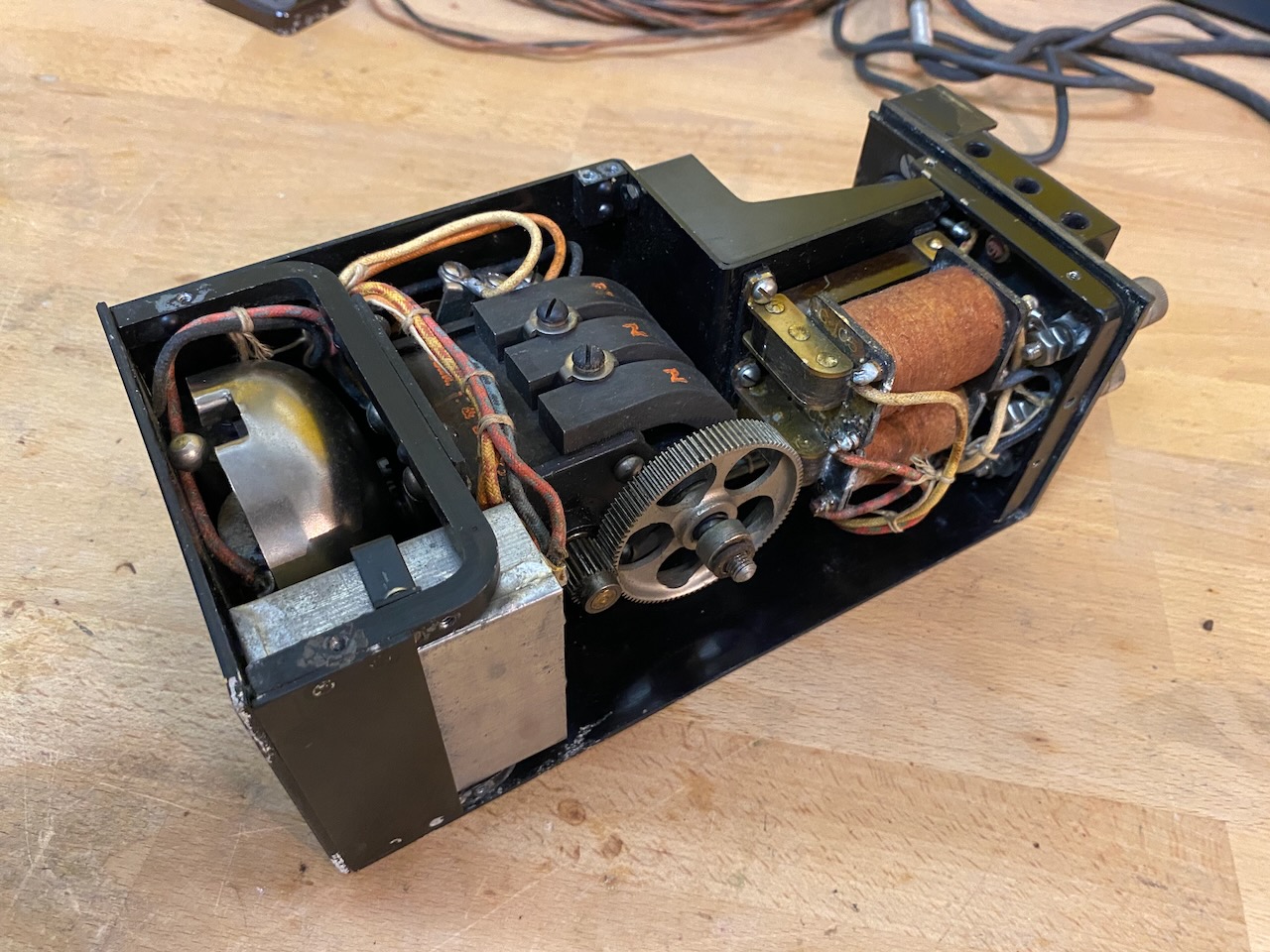
Generator GN-38 in the EE-8-A.
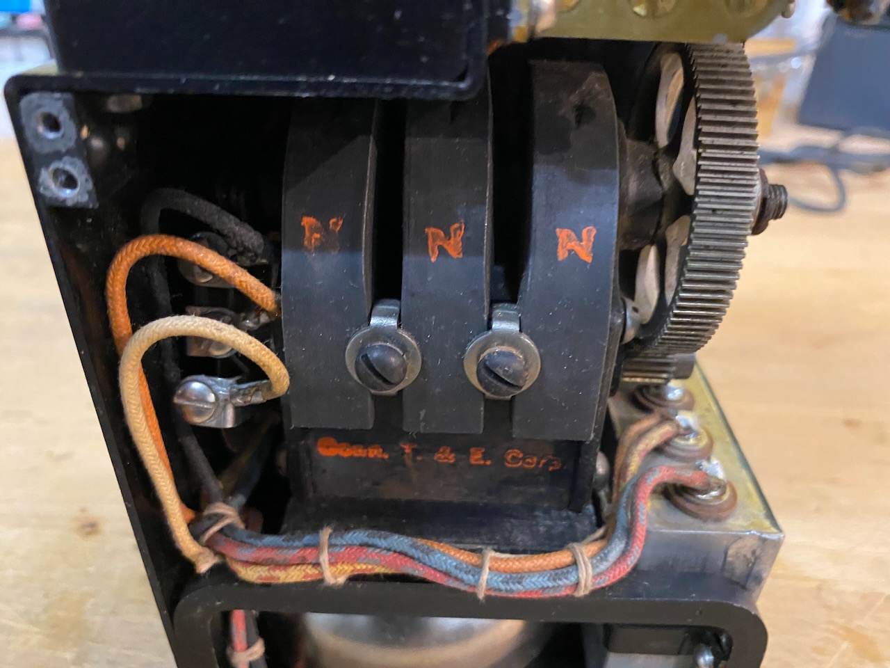
EE-8-B with generator GN-38-B.
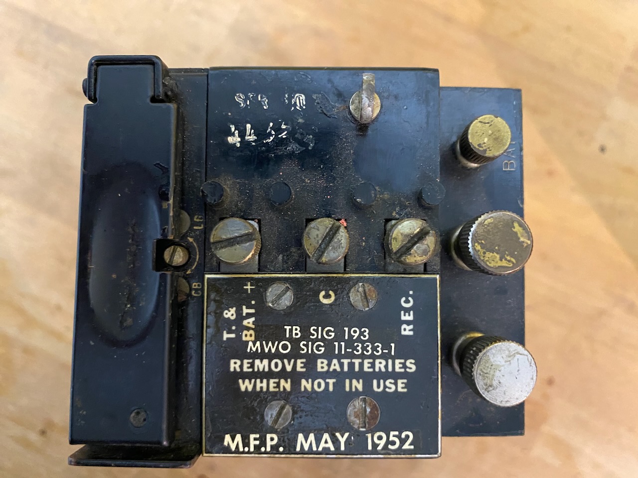
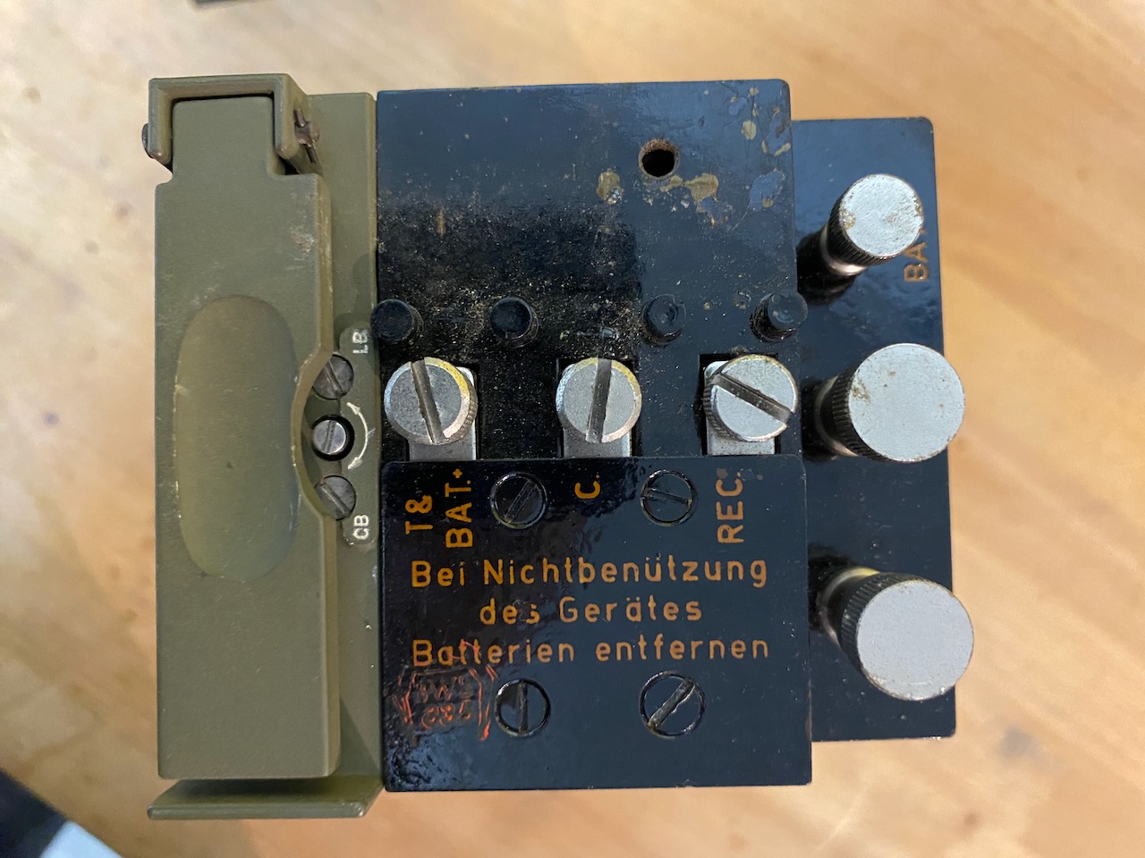
Terminal block EE-8-A, on the left the LB-CB screw and CB hook-lever.
In the middle three handset posts and to the right the line posts and the Bat- post.
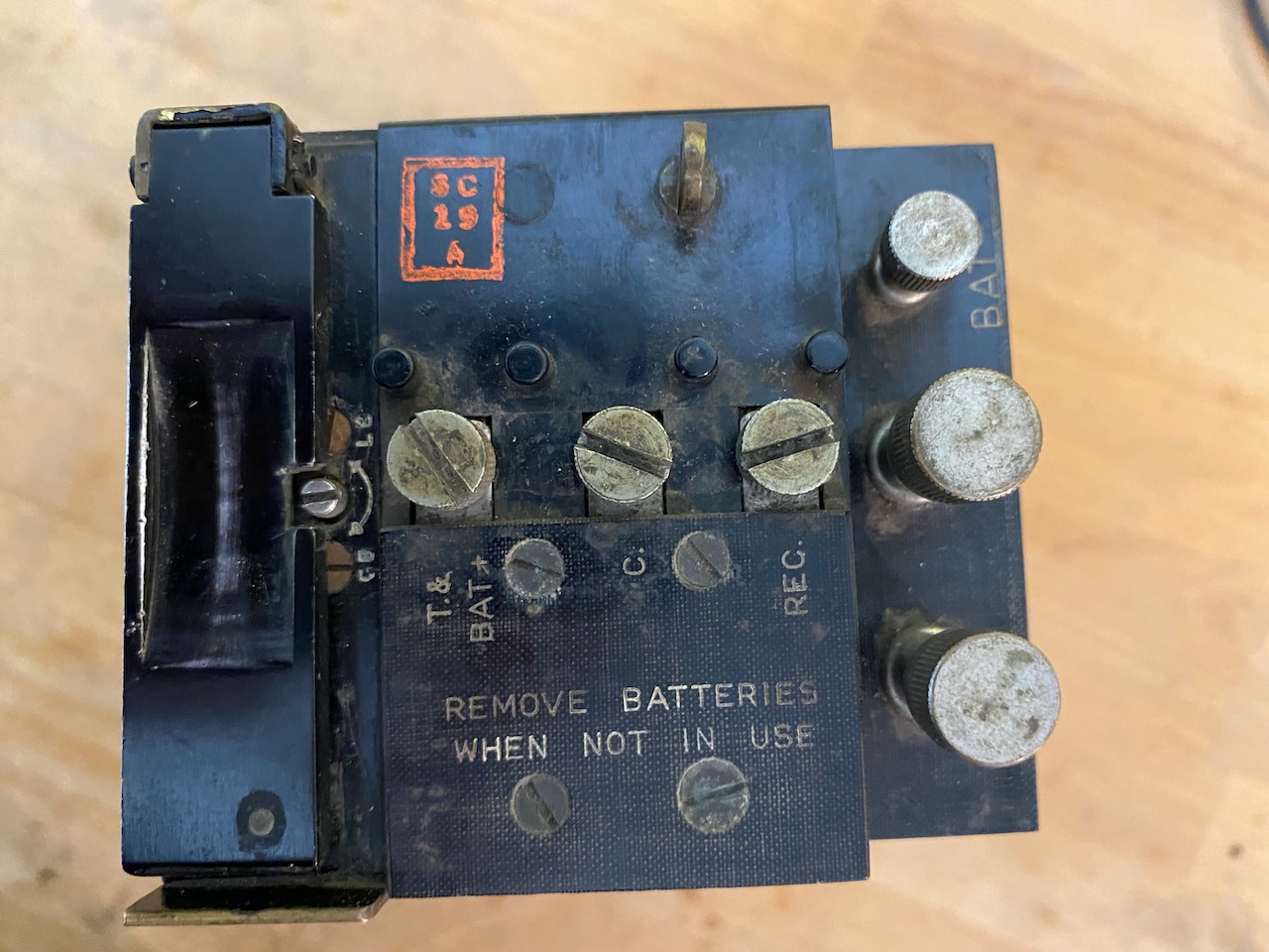
Terminal block EE-8-B, on the left the LB-CB screw and CB hook-lever.
M.F.P. (Moisture and Fungi proofing) treated in 1952.
In the middle three handset posts and to the right the line posts and the Bat- post.
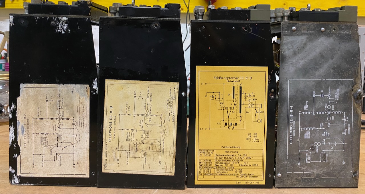
Left side view with circuit diagram.
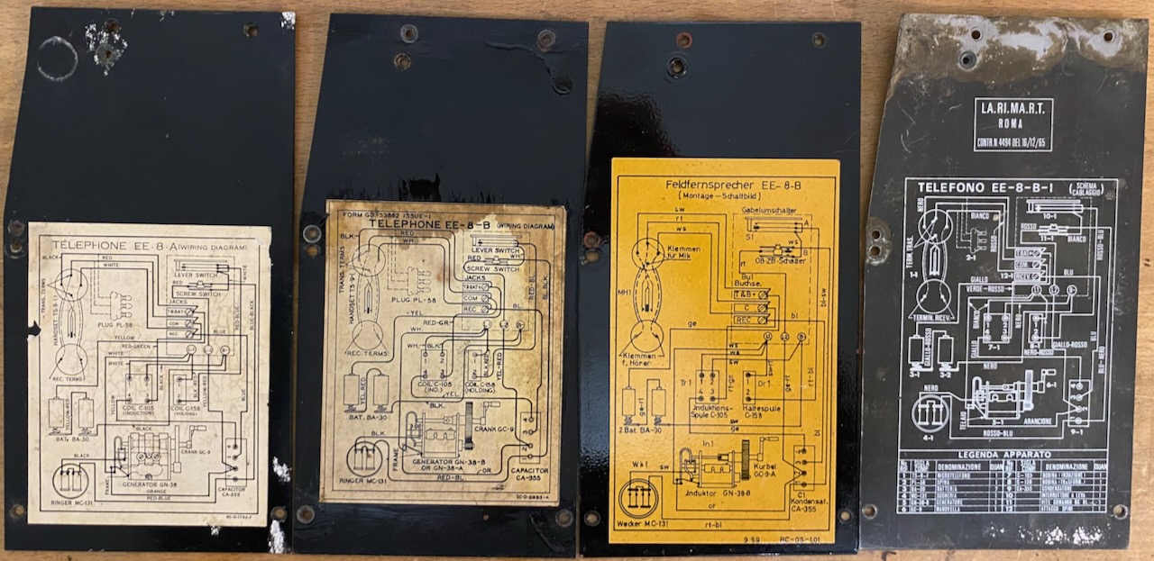
Right side sheet with wiring diagram.
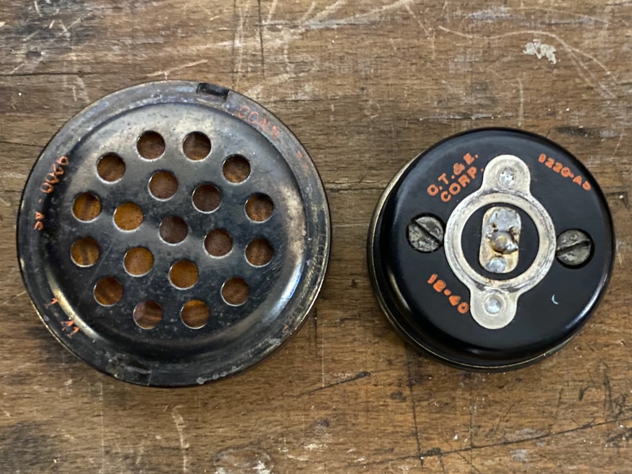
TS-9-E handset from the Connecticut Telephone & Electric Company EE-8-A.
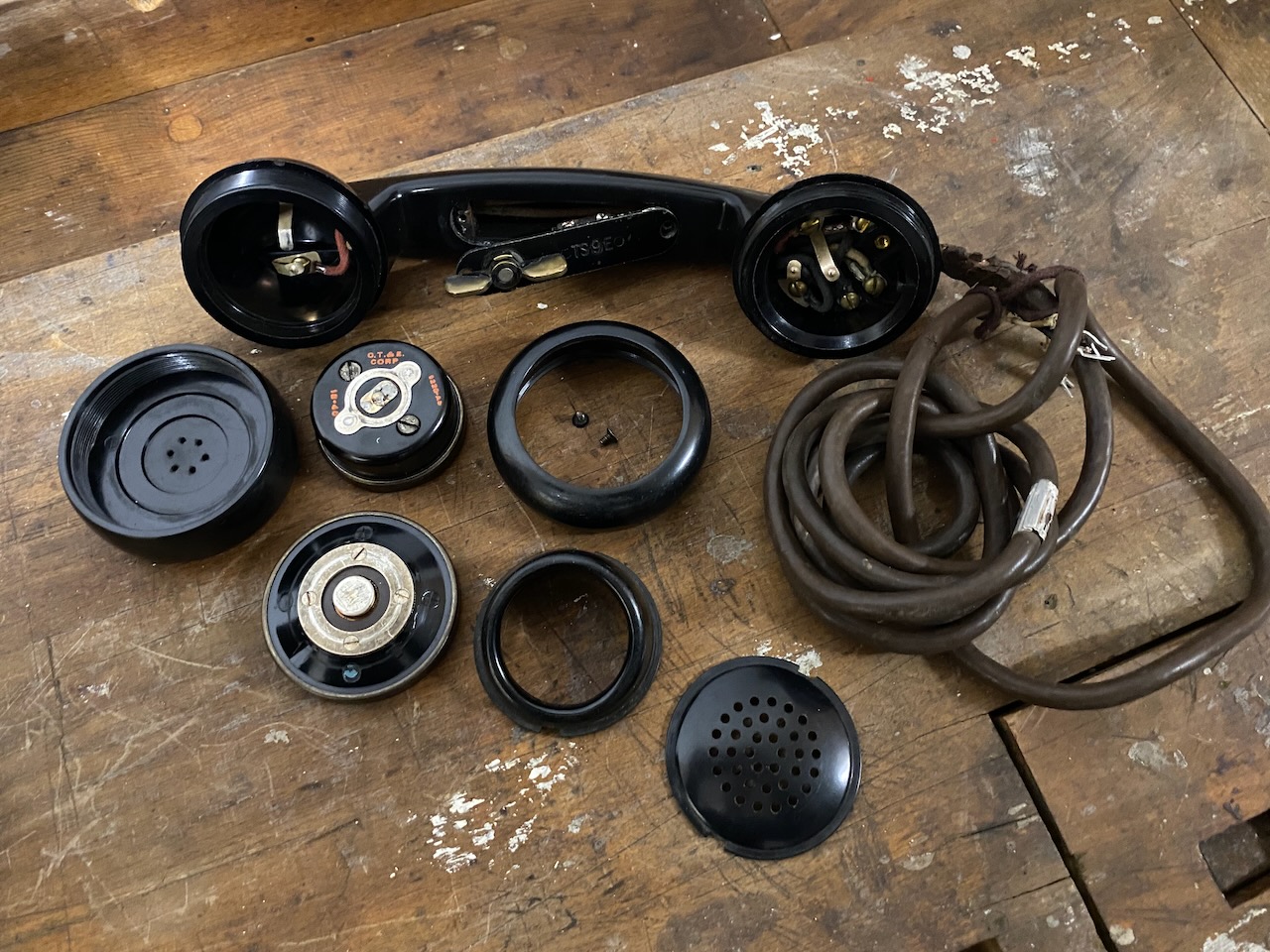
RX and TX elements made by Connecticut Telephone & Electric Company.
TS-9-(*) maintenance must have been somewhat a nightmare, as every manufacturers handset used their manufacturer specific RX and TX elements.
Kellogg made TS-9-K handset from the Automatic Electric EE-8-B.
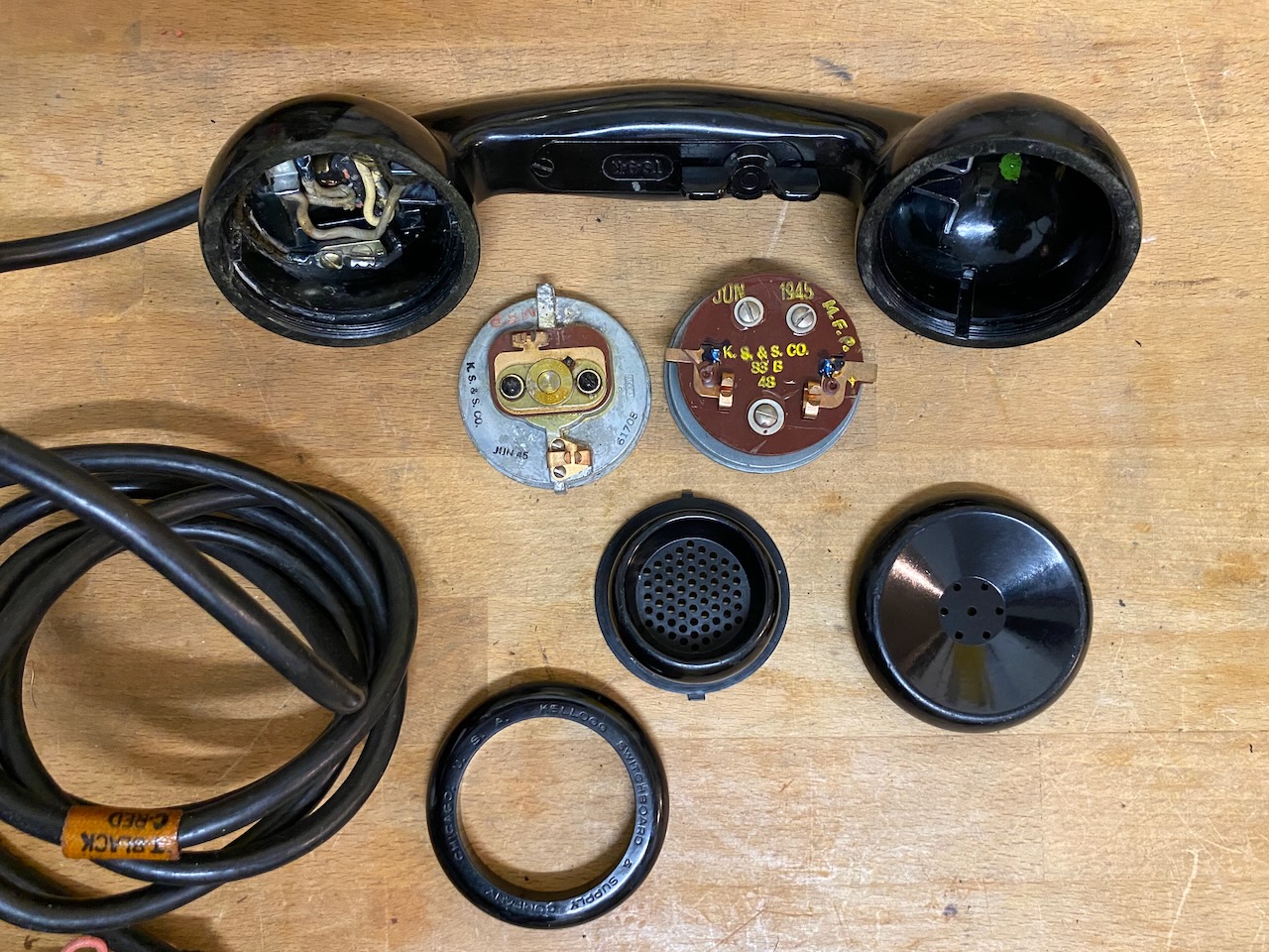
RX and TX elements made by Kellogg.
Back view.
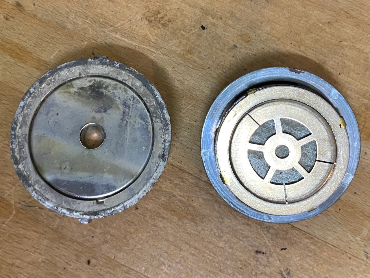
TS-9-(*) maintenance must have been somewhat a nightmare, as every manufacturers handset used their manufacturer specific RX and TX elements.
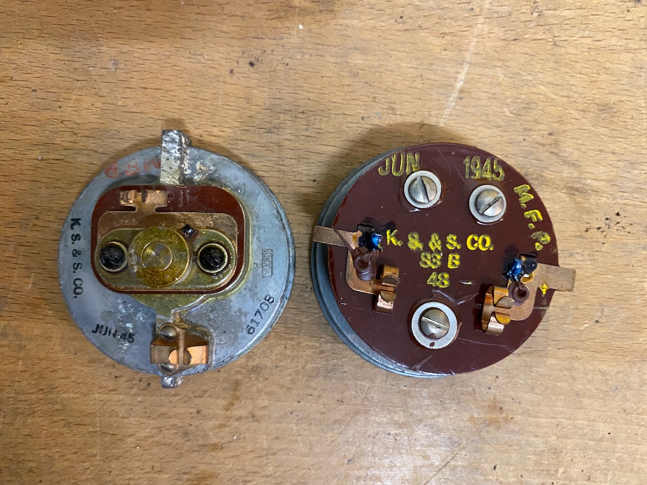
RX and TX elements made by Kellogg.
Front view.
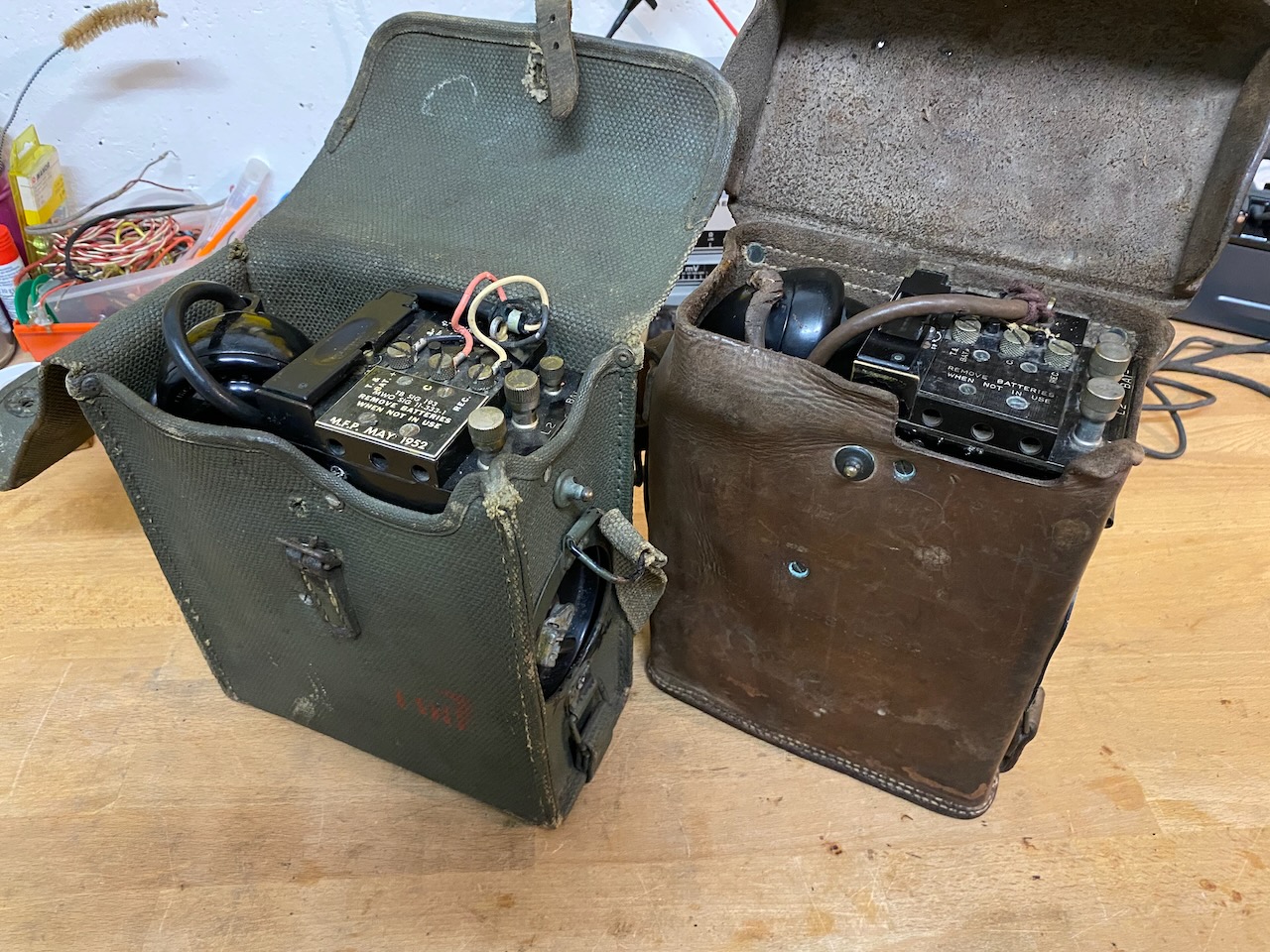
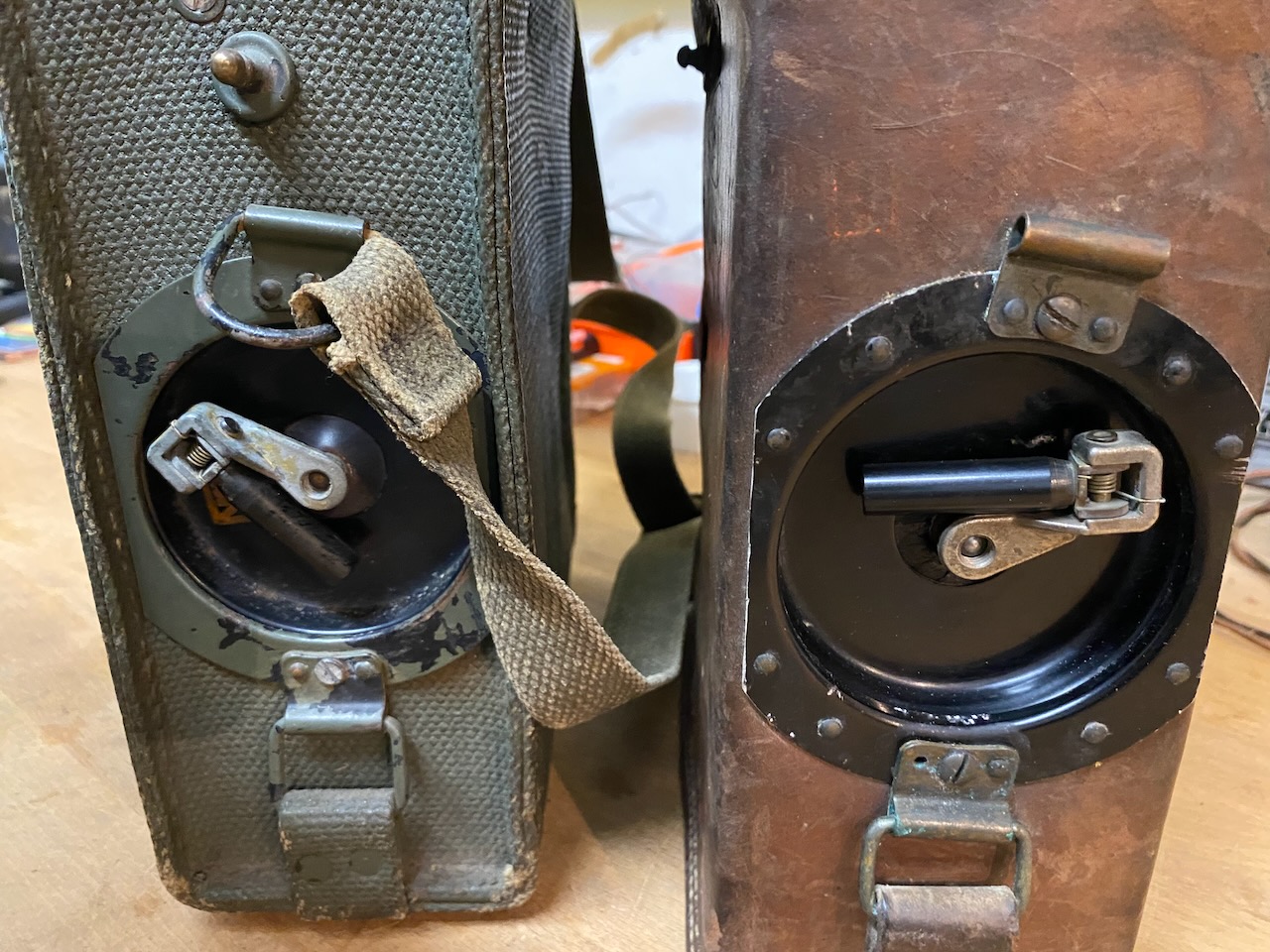
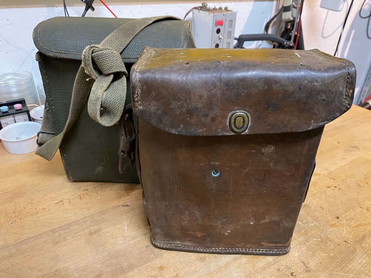
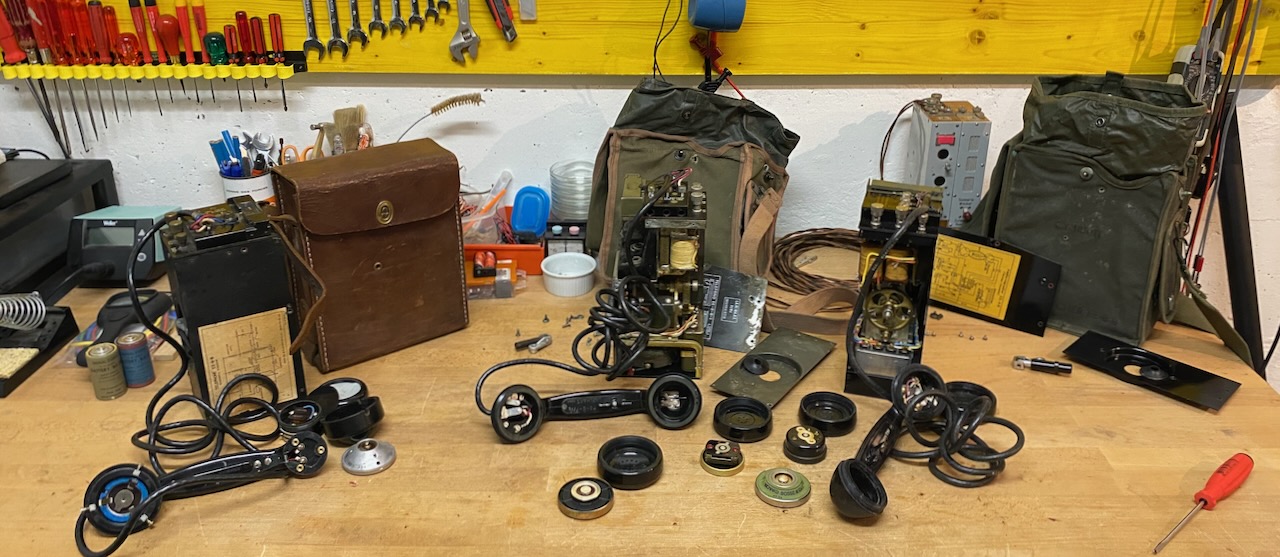
Neatly arranged EE-8-B (Canvas) and EE-8-A (Leather).
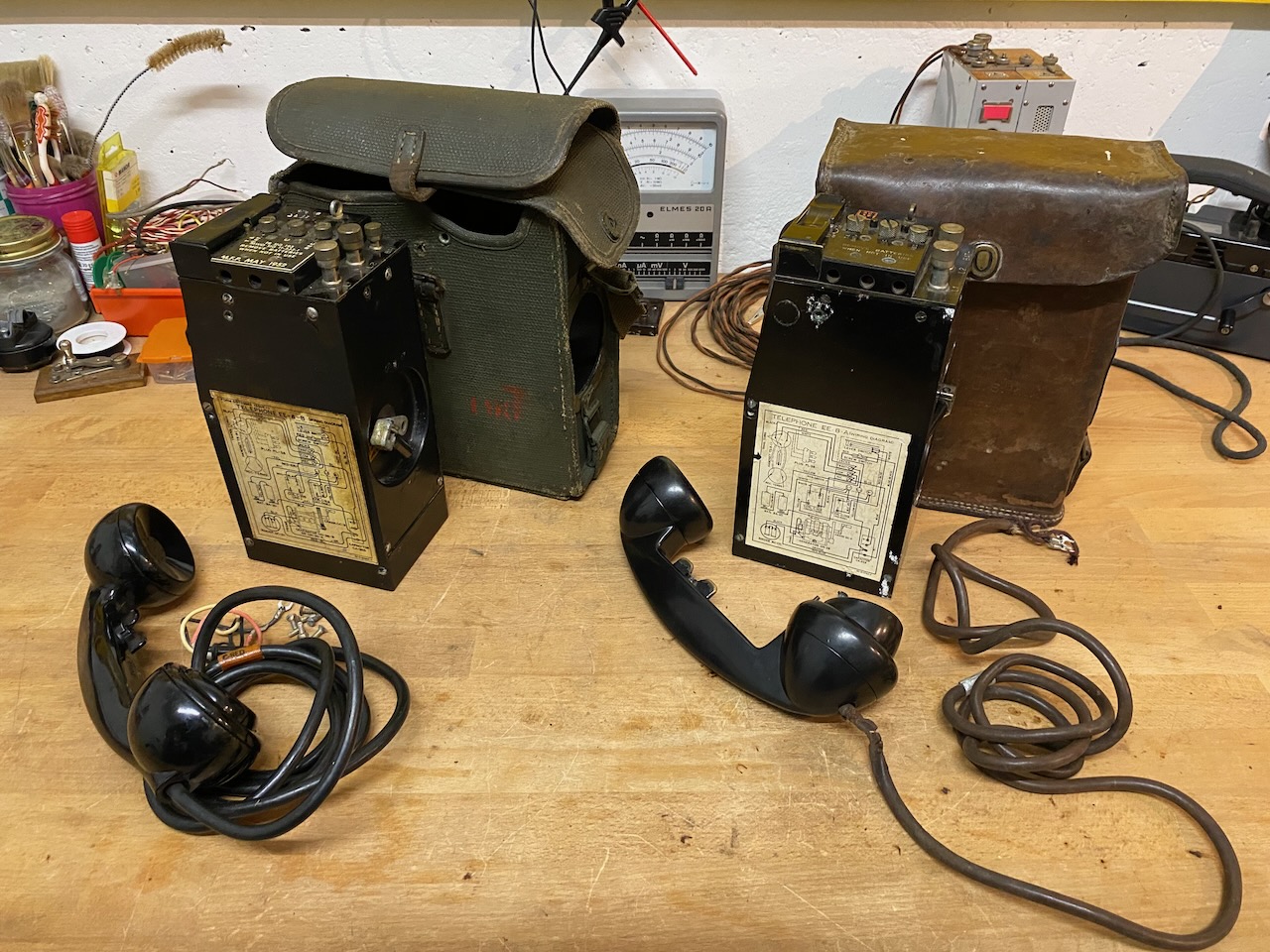
Ready for use, with handset resting on CB hook-switch.
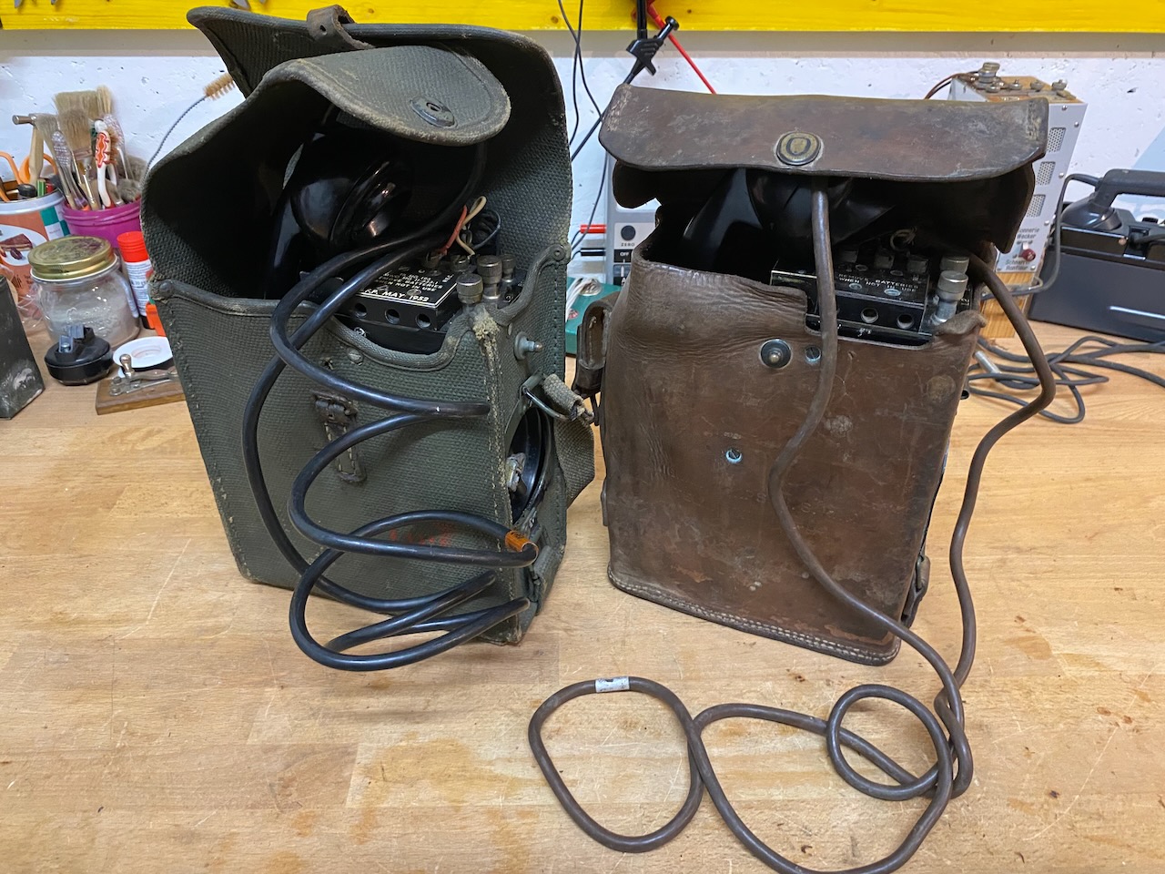
Handsets stored.
Magneto crank side.
Ready for transport.
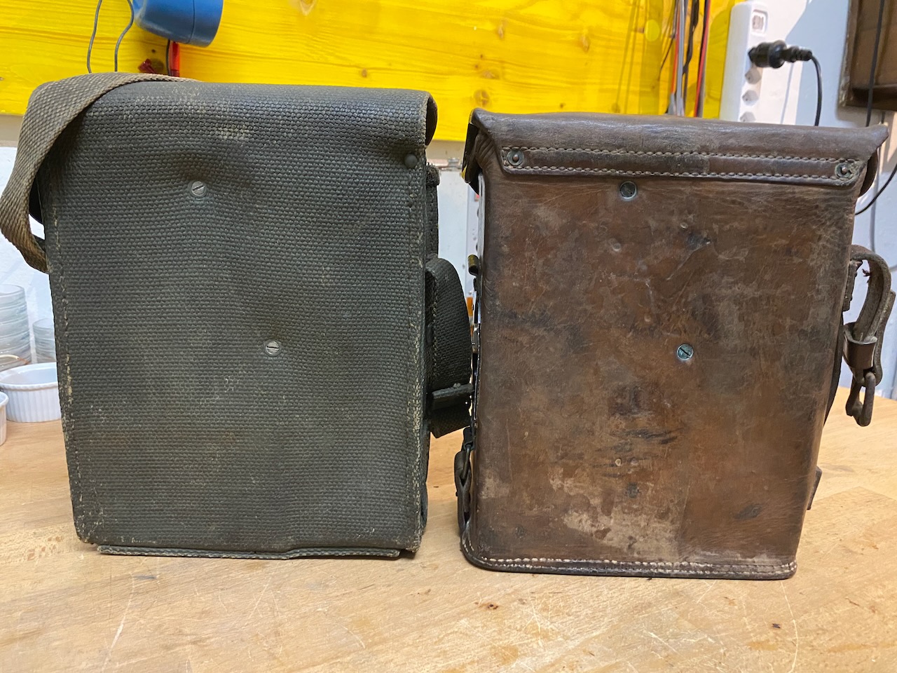
Back view.
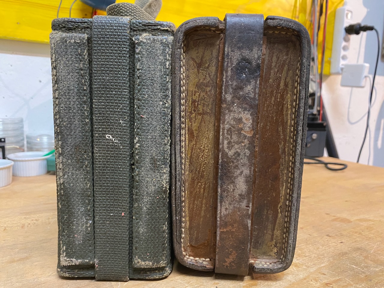
Bottom view.
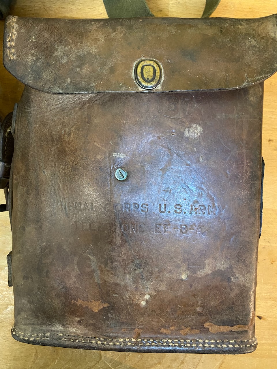
On the leather covers the model is embossed: "Signal Corps U.S. Army Telephone EE-8-A".
French EE-8-B (refurbished body with a local french handset (made by Depaepe) and french leather case), Italian made EE-8-B-I (Made by LA.RI.MA.R.T.), German made EE-8-B (Made by Bauknecht-GEA and Richard Bosse & Co.).
Wiring diagram on the French device which seems to be a refurbished US device, french wire colours have been added by manual notes.
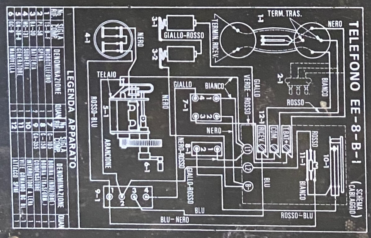
Italian wiring diagram.
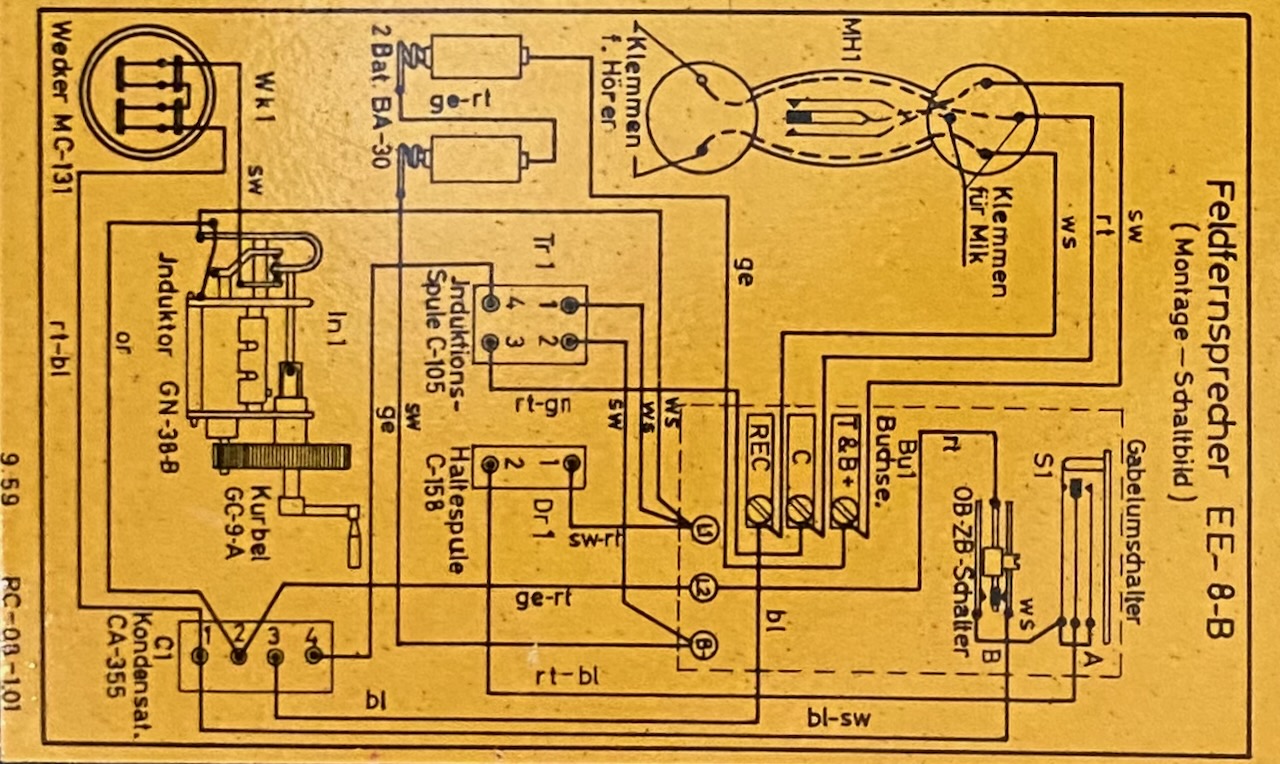
German wiring diagram.
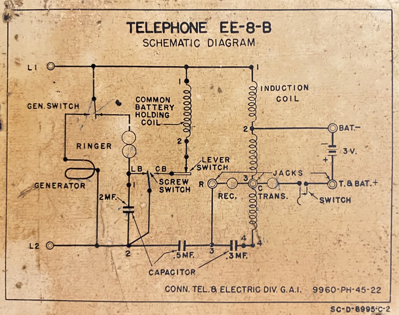
Circuit diagram on the "French" device, made by Connecticut Telephone & Electric Company.
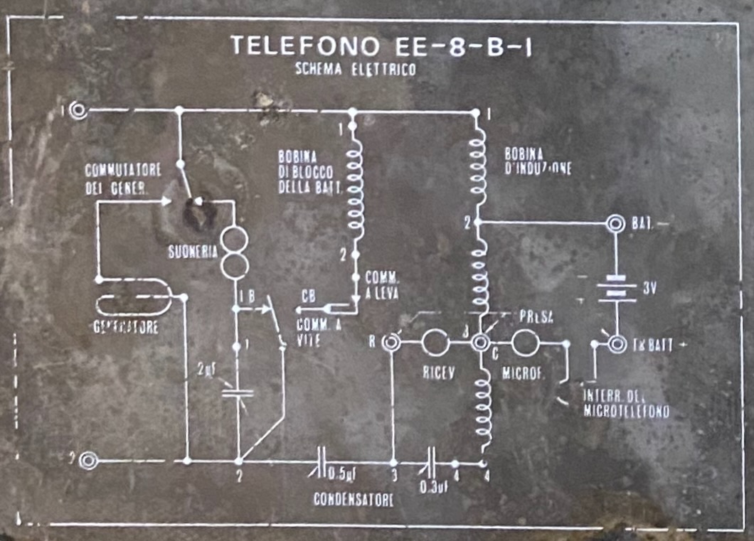
Italian circuit diagram.
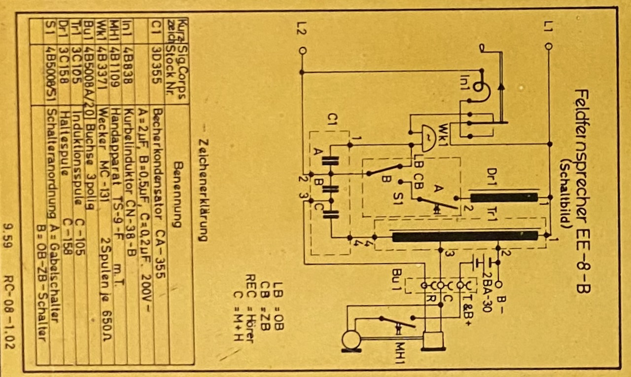
German circuit diagram.
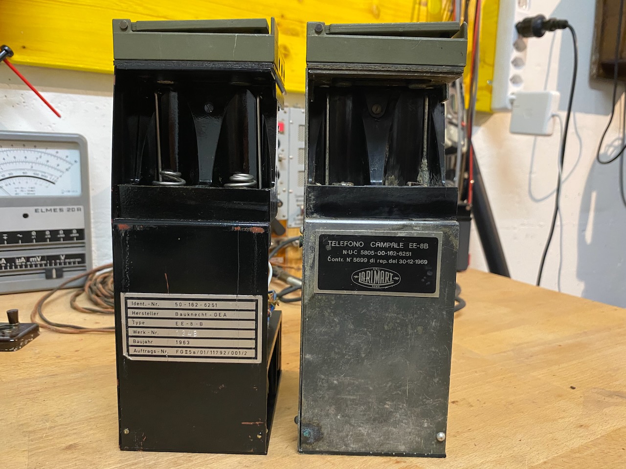
German and Italian chassis, with manufacturer labels from Bauknecht-GEA, 1963, and LA.RI.MA.R.T., 1969.
Open chassis of Italian model.
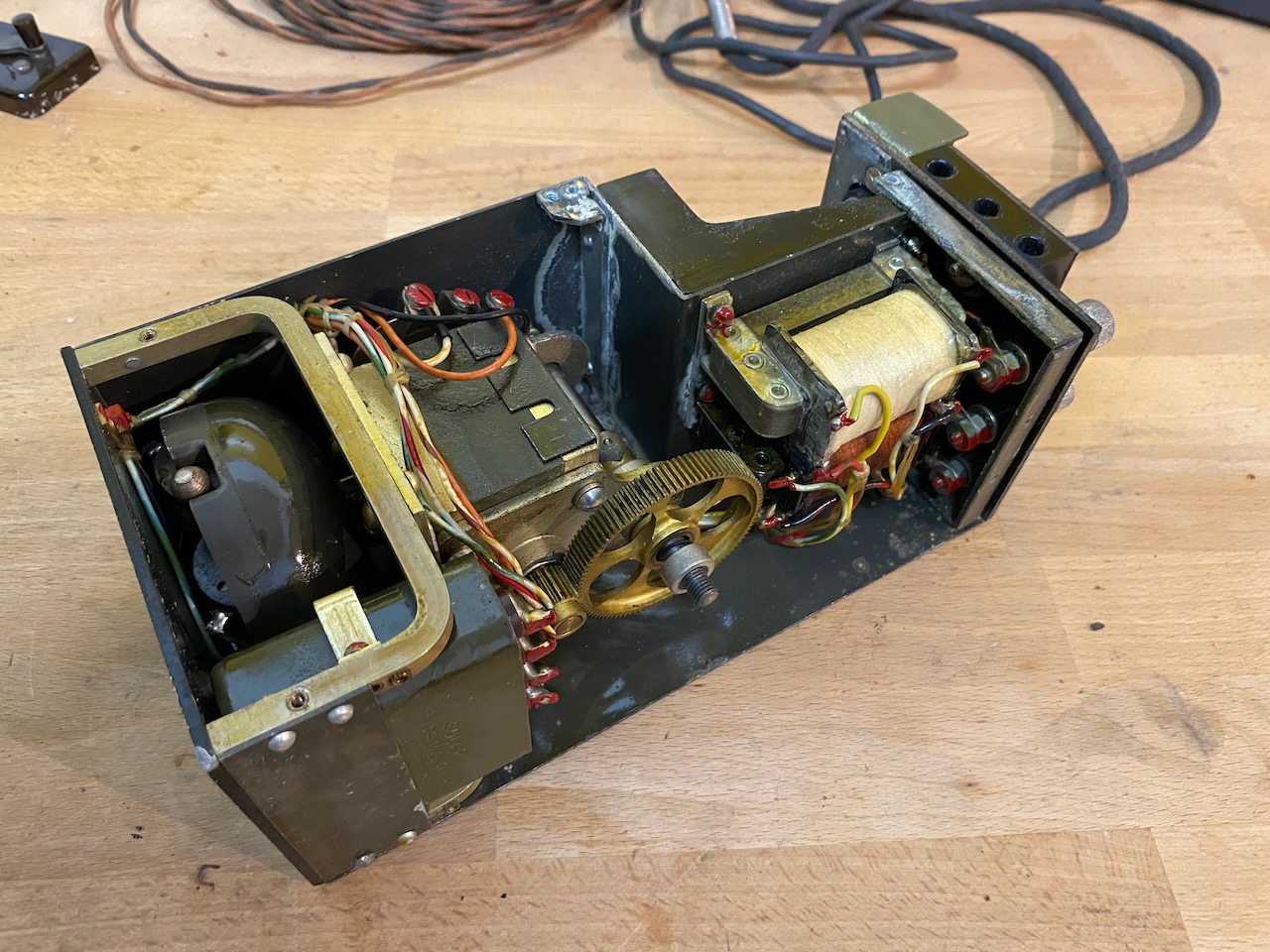
Open chassis of German model, Magneto made by Richard Bosse & Co..
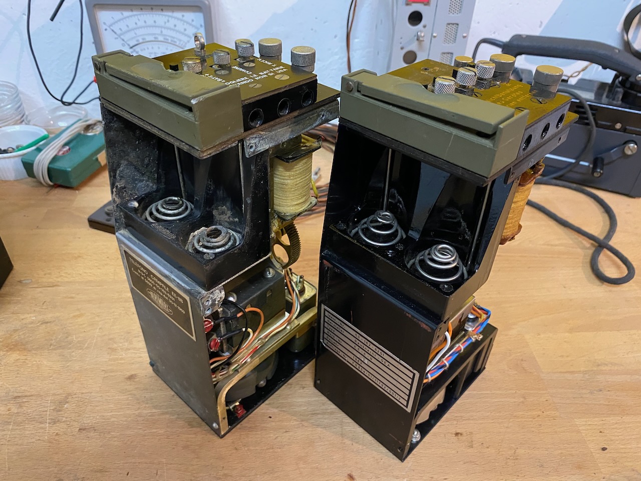
Battery compartment view.
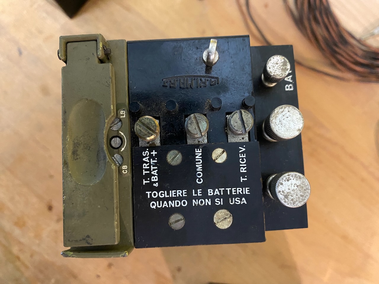
Terminal block view of Italian model.
Terminal block view of German model.
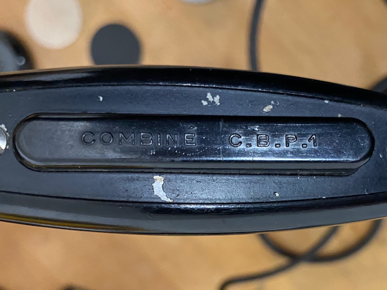
French handset, similar construction than French PTT models 1924, but with push-to-talk lever.
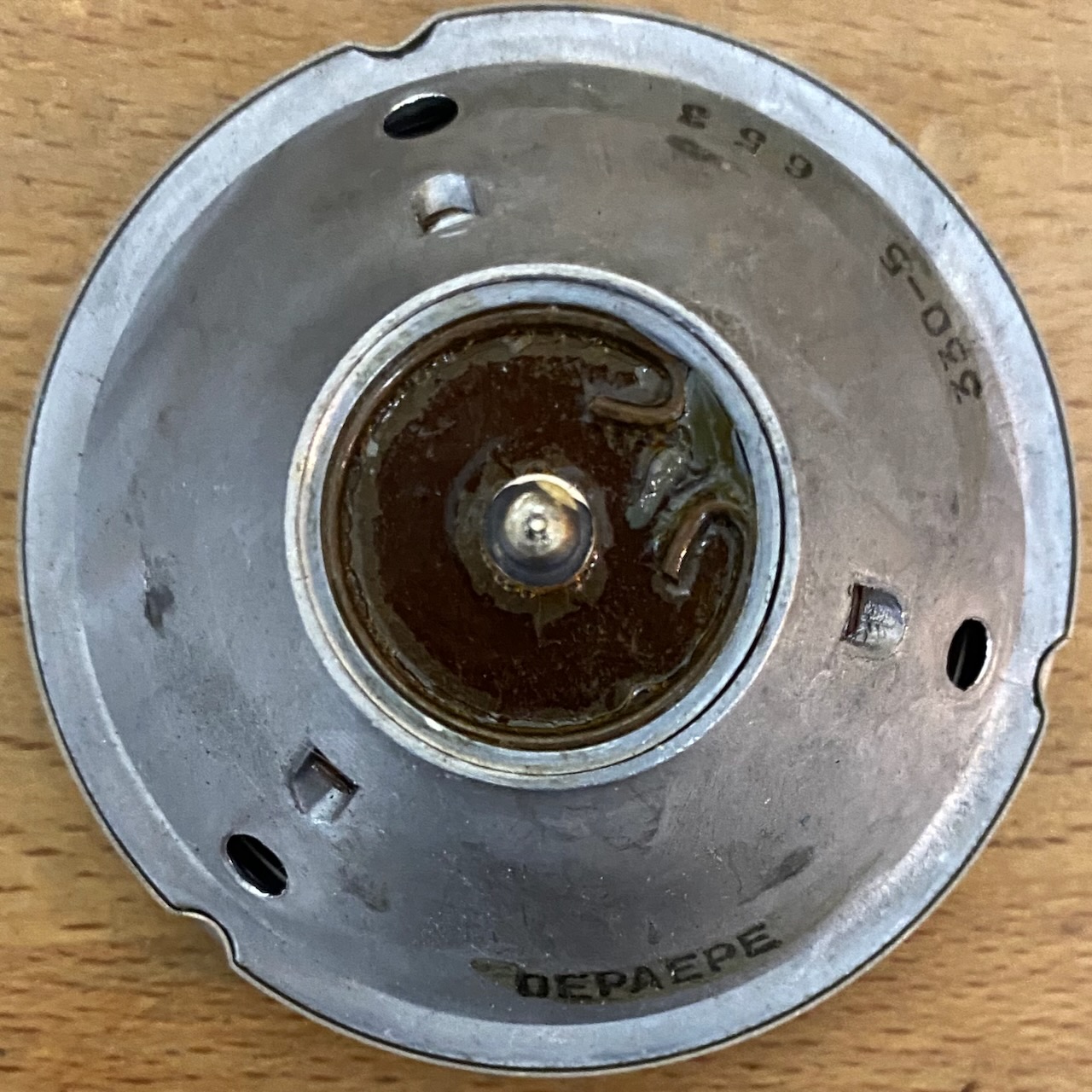
French TX element, made by Depaepe in 53.
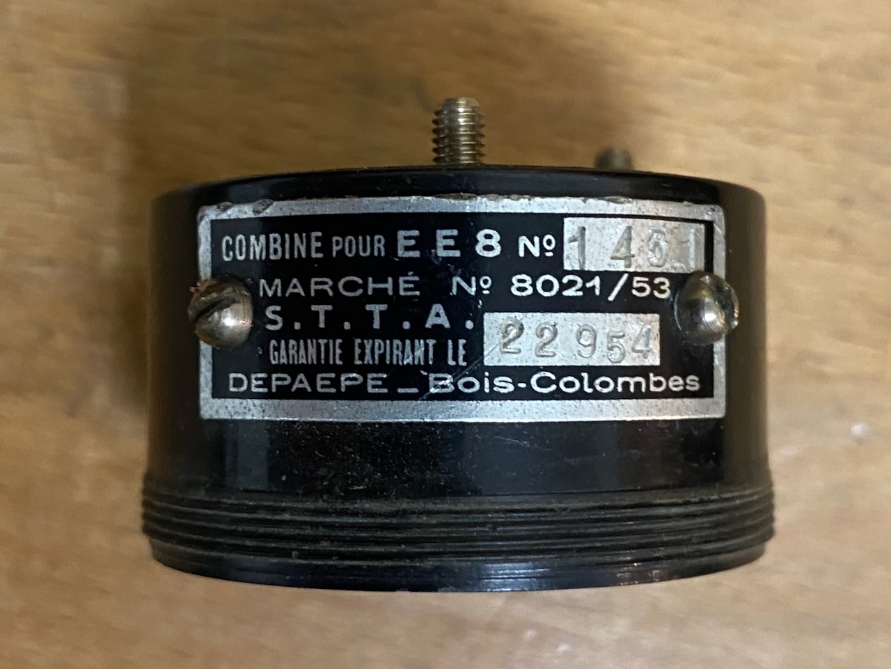
Label on French handset RX side: Made by Depaepe in 53, Model: "Combine pour EE8" (Handset for EE8).
French handset handle.
Model indication: "Combine C.B.P.1"
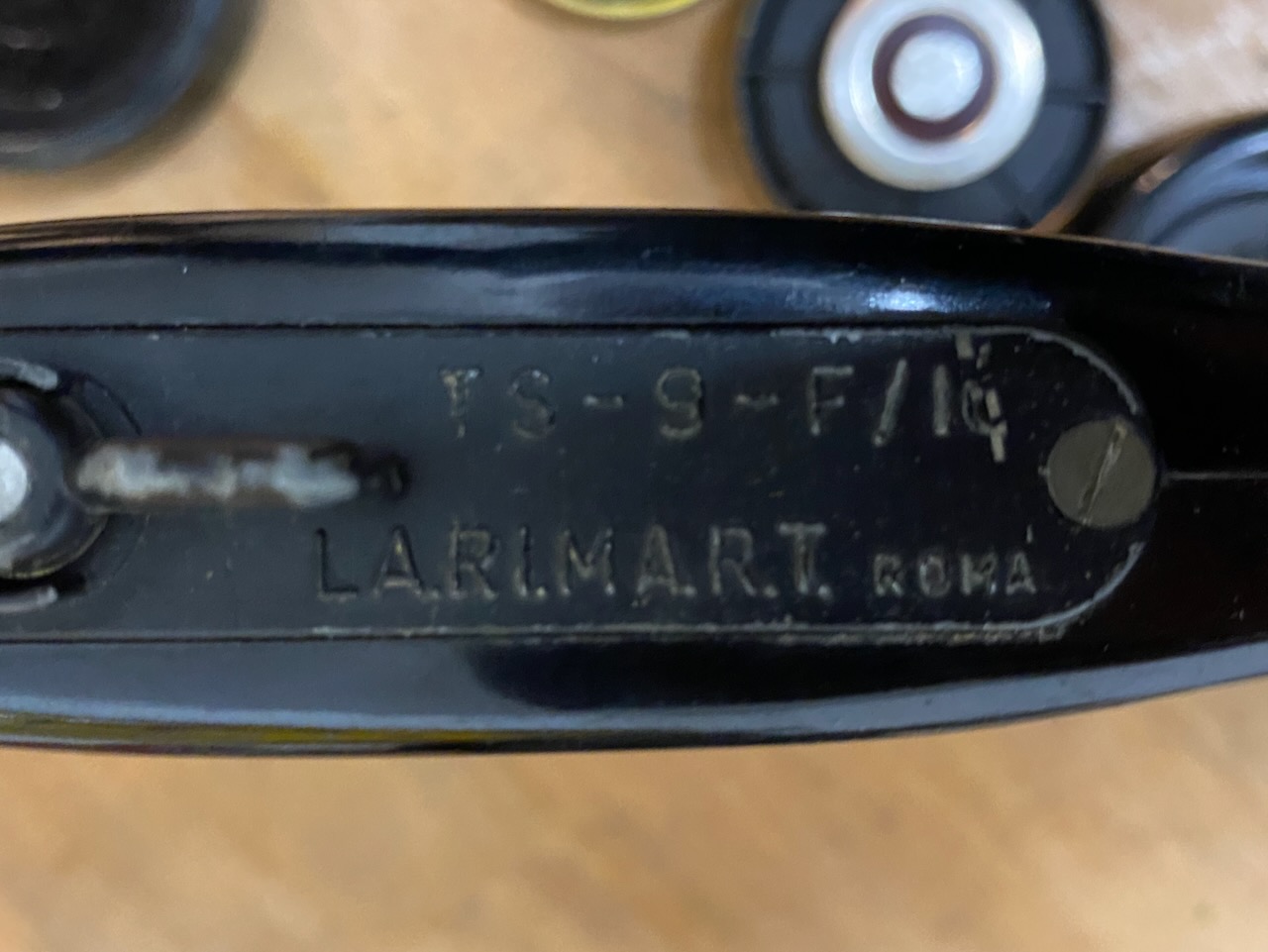
Italian Handset TS-9-F/I.
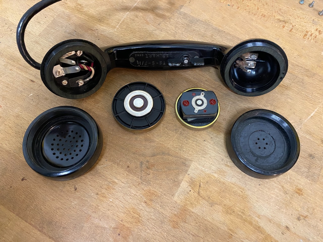
Made by LA.RI.MA.R.T Roma.
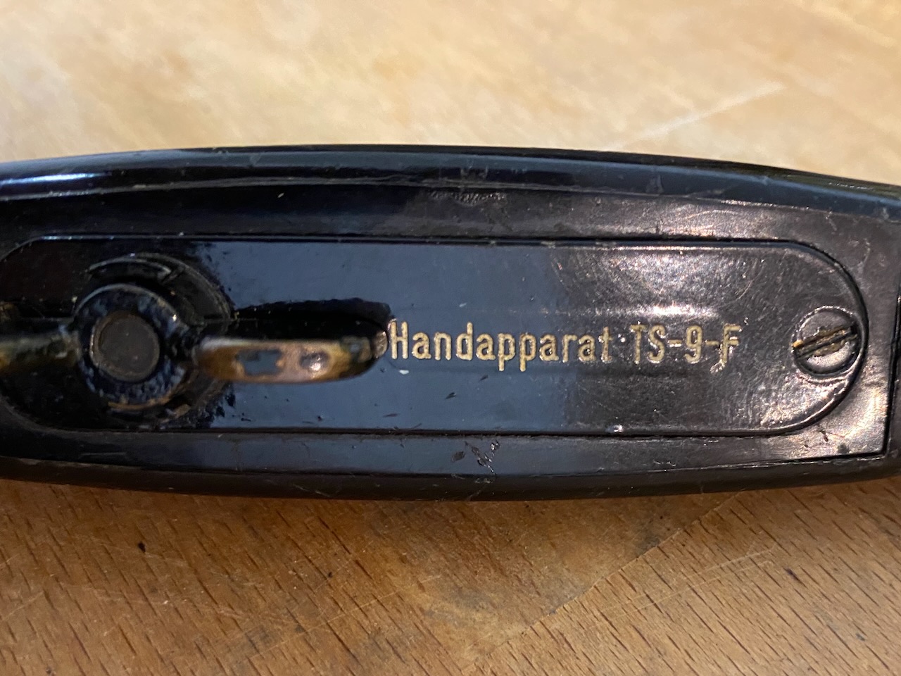
German Handset TS-9-F.
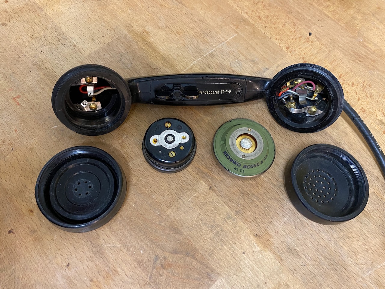
"Handapparat" TS-9-F.
Italian canvas pouch "Telefono EE-8-B".
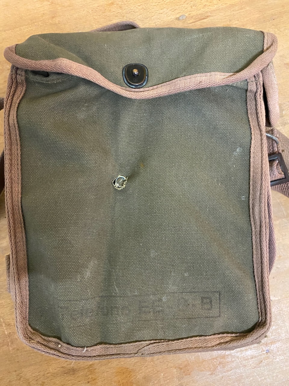
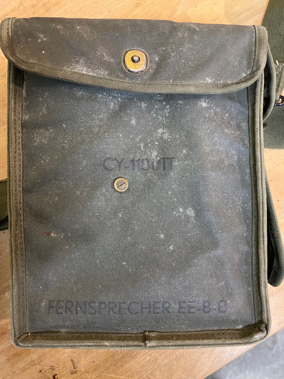
German canvas pouch "Fernsprecher EE-8-B".
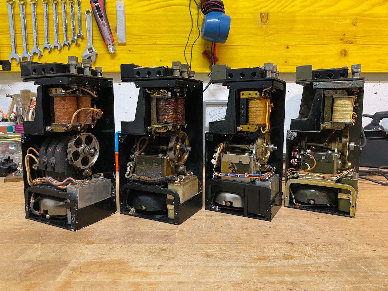
Open chassis from left to right: EE-8-A, EE-8-B, German, Italian.
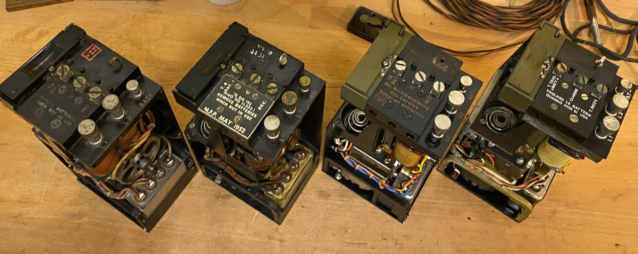
Top view from left to right: EE-8-A, EE-8-B, German, Italian.
Circuit diagram view from left to right: EE-8-A, EE-8-B, German, Italian.
Wiring diagram from left to right: EE-8-A, EE-8-B, German, Italian.
Creative Commons Attribution-ShareAlike 4.0 International License