
Find more details on U.S. field telephone history on the U.S. Signal Corps Field Telephones Timeline.
Thanks a lot to Ezesar for providing images of his SB-18/GT.
This extremely simple and lightweight U.S. Signal Corps switchboard was first introduced as the SB-18/GT in 1945, with the accompanying adapter plug U-4/GT possibly appearing as early as 1944 [2]. In 1960, the SB-18/GT and U-4/GT were replaced by the SB-993/GT and U-184/GT due to the use of radioactive luminescent material on the U-4/GT adapter plug. The newer models omitted luminescent labels in order to “aid in removing the radioactive items from the field and from the supply system” [7]. The equipment continued to be mentioned in regulations until the mid-1980s [10], but no longer appeared in documents from the 1990s [11].
Emergency Switchboard SB-18/GT and Adapter Plug U-4/GT [4]:
Emergency Switchboard SB-18/GT is a very light, highly mobile, emergency switching center for local battery telephone lines. With Telephone EE-8-( ) or Telephone TP-3 (sound-powered telephone) for an operator’s set, Emergency Switchboard SB-18/GT may serve as an emergency field replacement for a magneto switchboard. The Small size, weight, and moisture proof characteristics of the SB-18/GT suggest its use in jungle, mountain, amphibious, and air-borne operations. Adaptor Plug U-4/GT also may be used to substitute a silent visual signal for the audible magneto line signal provided in the ringer in either telephone. Telephone EE-8-( ) can operate the signal in Adapter Plug U-4/GT over distances up to 20 miles on Wire W-110-B.Adapter Plug U-4/GT [5]:
Adapter Plug U-4/GT is a jack-plug combination mounted in a transparent plastic body. A 50,000-ohm resistor and a .1-watt neon lamp are wired in series across the plug-jack combination and placed within the body. The minimum signaling voltage for the adapter plug is 65 volts alternating current. [...] Embedded below an etched surface of the plug is a luminous identification strip of a white plastic material over which identification numbers may be written. A luminous dot indicates the plug end of the adapter plug, facilitating operation in darkness [...].
Operation under usual conditions [5]:
- Line-to-line Connection.
- When the neon lamp flashes in the adapter plug of a calling telephone, insert the operator’s adapter plug into the jack end of the adapter plug of the calling telephone. Use the operator’s telephone to answer the calling telephone.
- Determine the number to be called and remove the operator’s adapter from the jack of the calling telephone. Insert the operator’s adapter plug into the jack of the adapter plug of the called telephone.
- Use the hand generator on the operator’s telephone to ring the called telephone.
- When the called telephone answers, insert the adapter plug of the called telephone into the adapter plug of the calling telephone and report the connection ready.
- Do not remove the operator’s adapter plug until conversation has begun.
- To supervise any connection, insert the operator’s adapter plug into the adapter of the called telephone.
- A re-call or ring-off will be denoted by the neon lamp flashing in both adapters.
- Conference Connection.
- To set up a conference connection, use the operator's adapter plug to call each telephone individually.
- Inform the called telephones to stand by for a conference call and connect each adapter in parallel.
- After all of the desired telephones are connected, inform the calling telephone that the conference is established.
- On a re-call by any telephone in the conference connection, the neon lamps of all of the line plugs connected will flash.
- Supervise the connection on a recall or ring-off, challenge, and disconnect or change the connection as desired.
Operation under unusual conditions [5]:
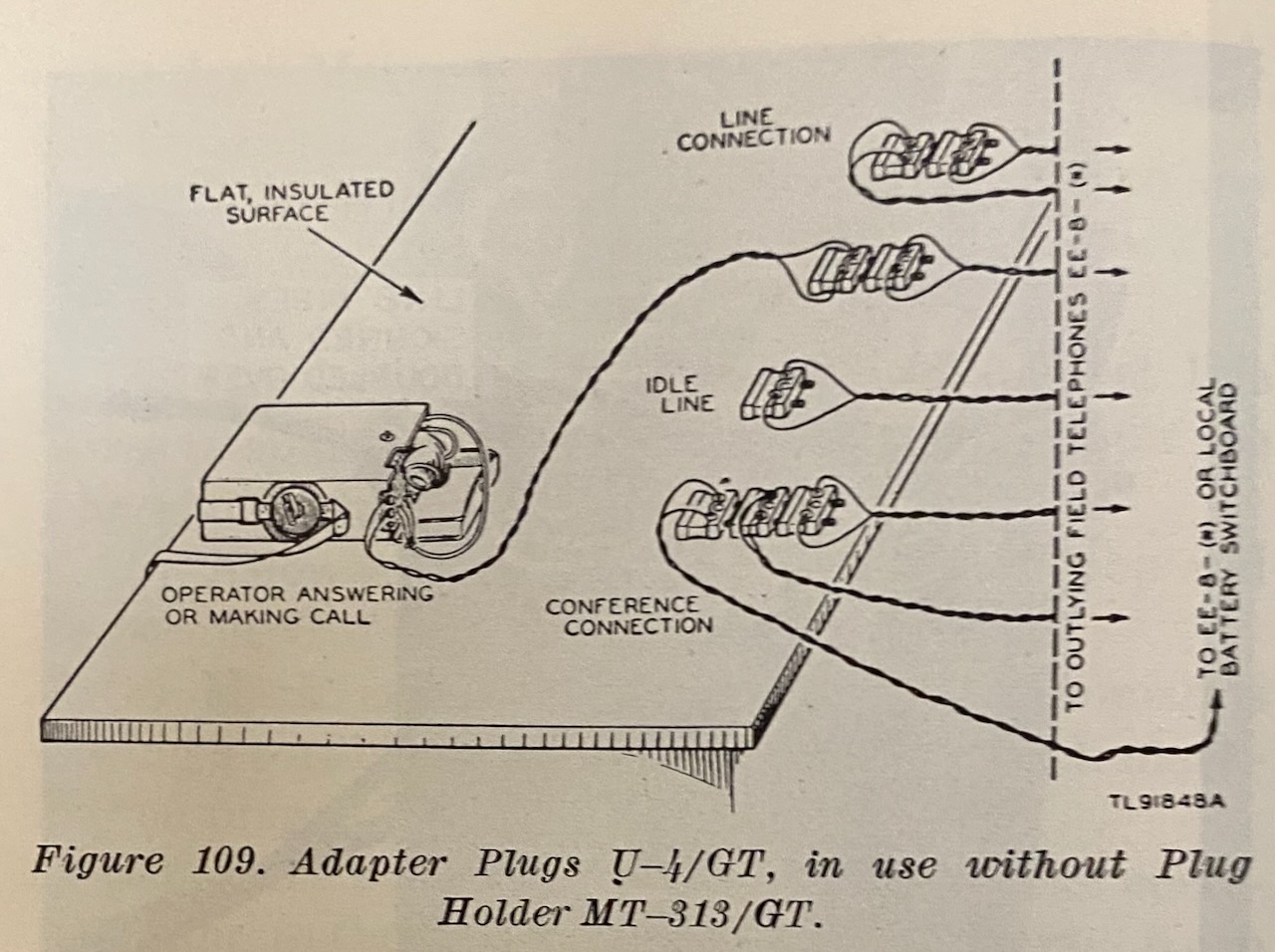
If Plug Holder MT-313/GT becomes damaged or is not available, operation may be performed by using only the adapter plugs and the operator’s telephone in the following manner:
- Select a dry, insulated surface and place the adapter plugs and the operator's telephone in a convenient line.
- Test the adapter plugs.
- Connect the line wires to the adapter plugs in such a manner that the wires enter the plugs on the sides which contain the luminous strips.
- Follow the procedures outlined in paragraph [above "usual conditions"] for operating instructions.
Emergency Switchboard SB-993( )/GT [8]:
- Emergency Switchboard SB-993( )/GT is a light, portable local battery switching center normally used in company-size units. It consists of a plug holder and seven two-pronged Adapter Plugs U-184( )/GT in a case. A field telephone is required for the operator's use. The SB-993( )/GT may be used as an emergency field replacement for any local battery switchboard.
- Each Adapter Plug U-184( )/GT (fig. 114) consists of a neon glow lamp, two binding posts, two plugs, and two jacks, all molded together in a translucent plastic housing. The plugs serve as the thumbscrew ends of binding posts to which incoming lines are connected. The plugs may be inserted into the jacks of another Adapter Plug U-184( )/GT to establish a connection between two lines.
- Several Adapter Plugs U-184( )/GT can be connected in tandem for conference connections (several separate parties conversing at the same time).
- An incoming ringing signal lights the neon lamp in the switchboard plug connected to the line, for the duration of the signal. An audible signal is not heard when the neon lamp lights, unless the switchboard operator's telephone is connected to that line. Thus, the operator must be constantly watching for an incoming signal.
The adapter U-4/GT or U-184/GT can also be used as call indicator for any field telephone allowing to dampen or silence the ringer.
Find below the SB-18/GT gallery and the U-4/GT as visual ring indicator gallery.
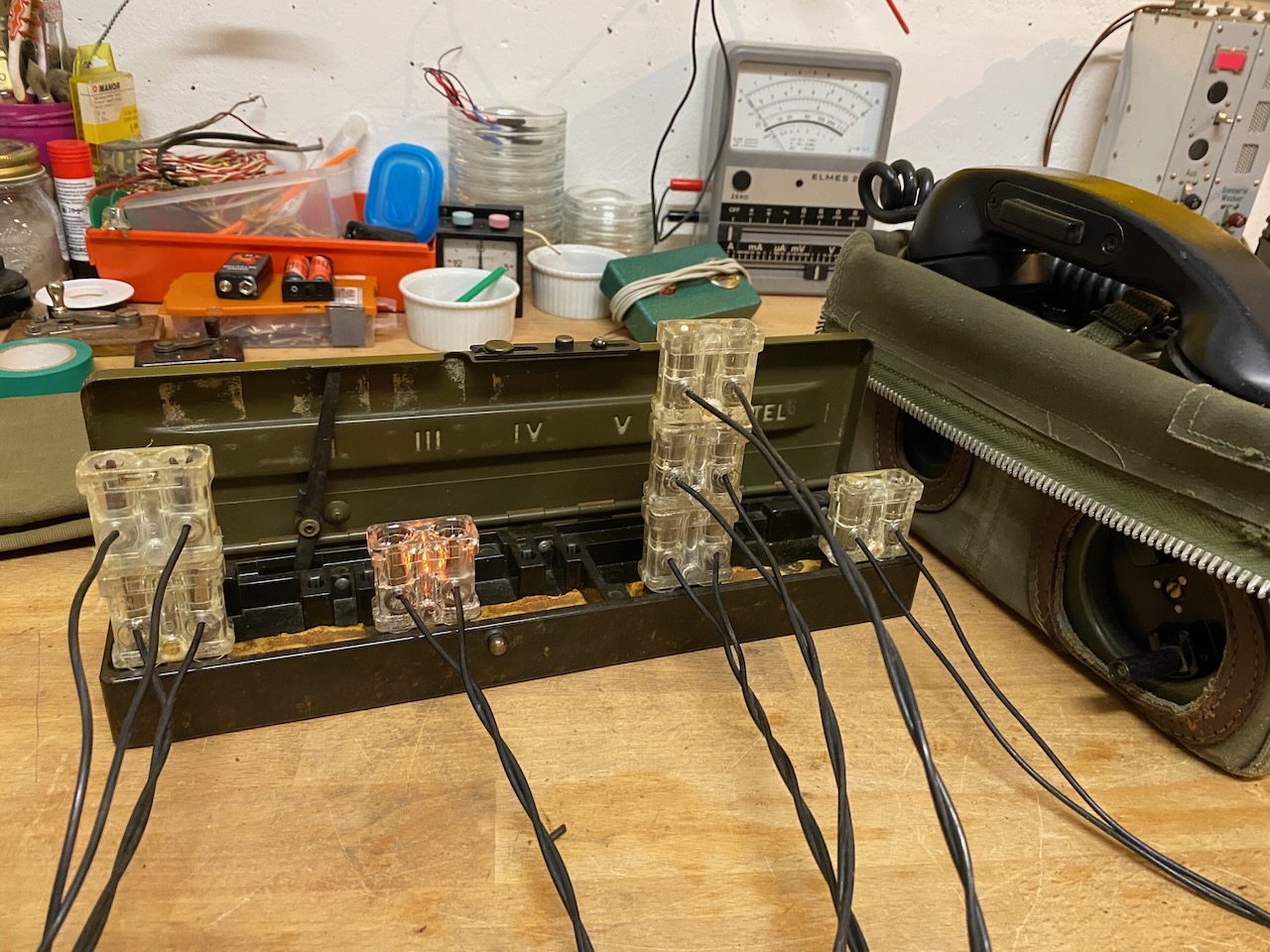
Ready to use, with a TA-43/PT as operator set.
In use.
Lines 1 and 2 are in a call.
On line 3 there is an incoming call so the neon light is active.
Lines 4, 5 and 6 are in a conference call.
The operator is idle but should answer soon on line 3.
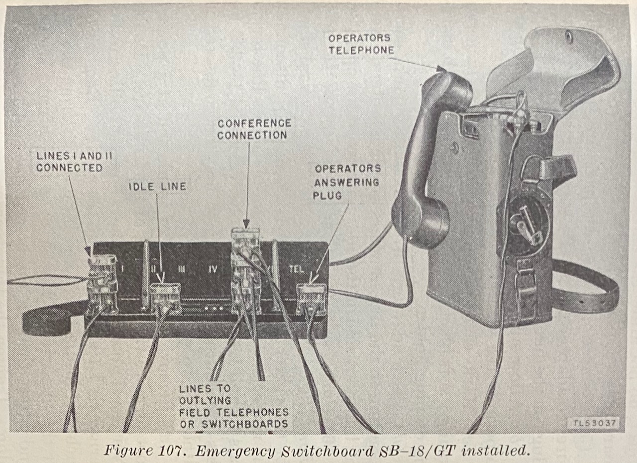
Usage example from FM24-20 1948 [5].
Usage example without holder, from FM24-20 1948 [5].
3 types of plugs.
From left to right:
U-184/GT, Nanasi, ~60ies.
U-4/GT, S.C. (most prob. Stromberg-Carlson), ~50ies.
U-184/GT, New old stock, Star Dynamic, ~80ies.

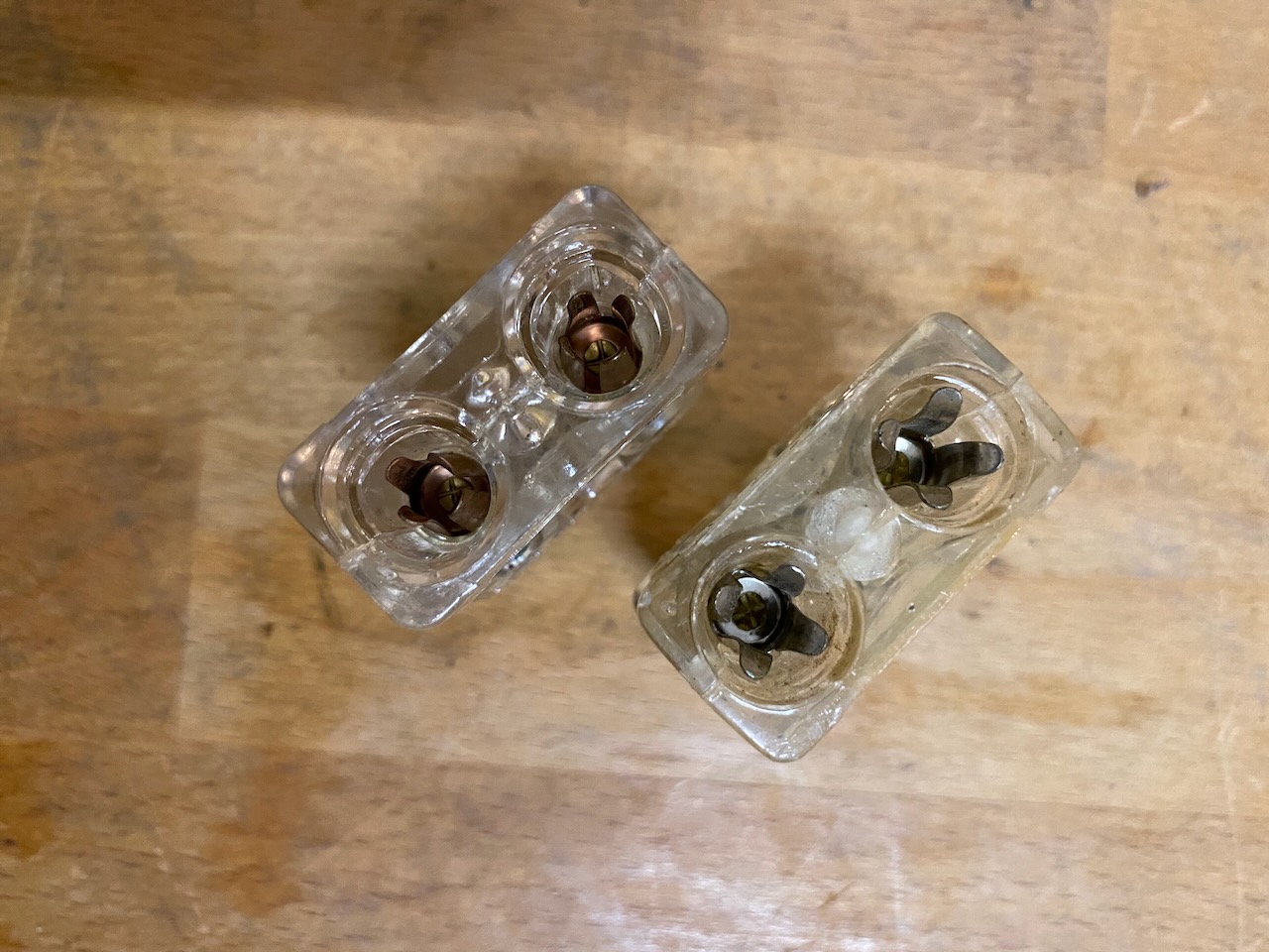
Plugs from above, socket side.
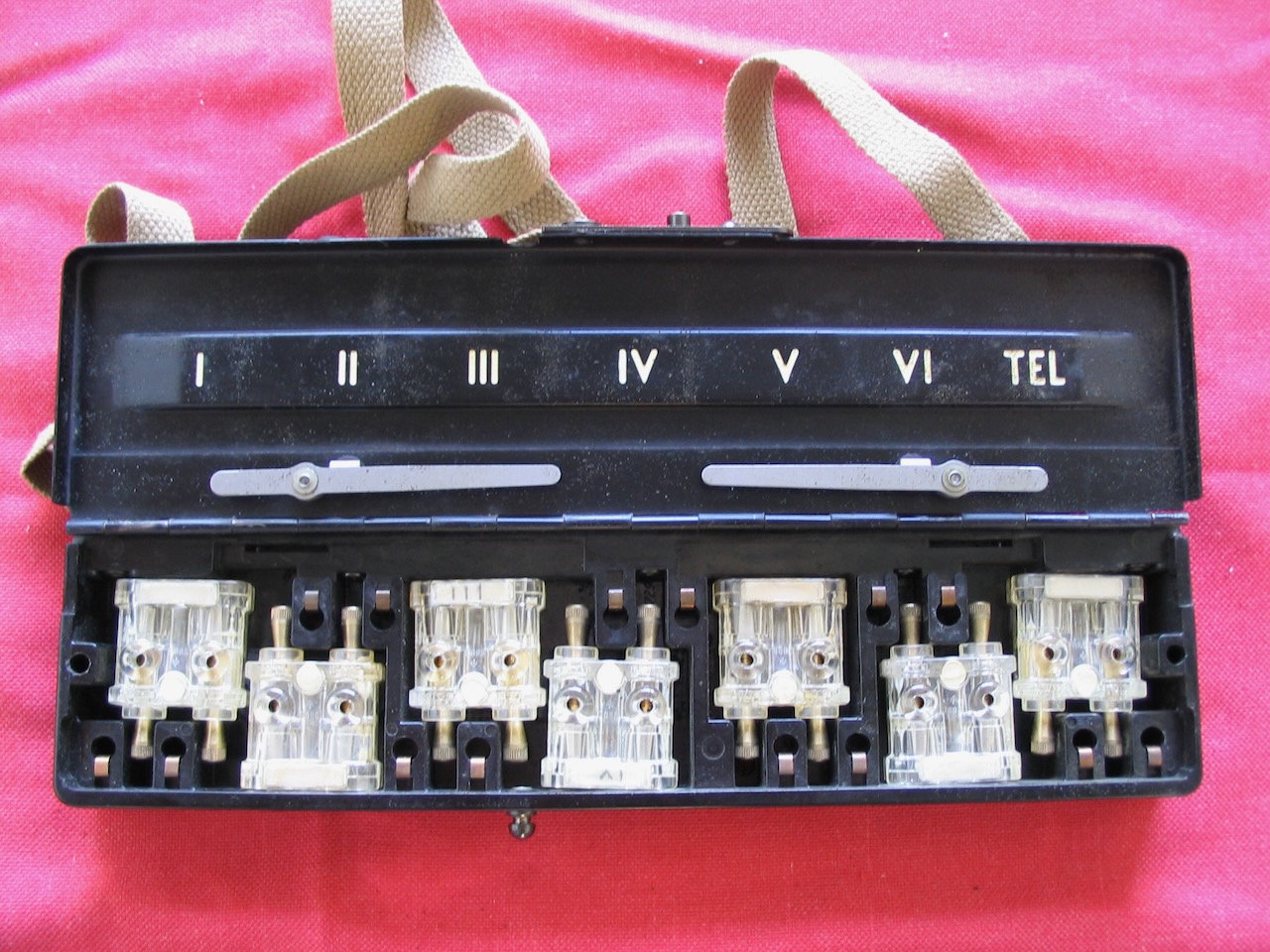
All plugs in.
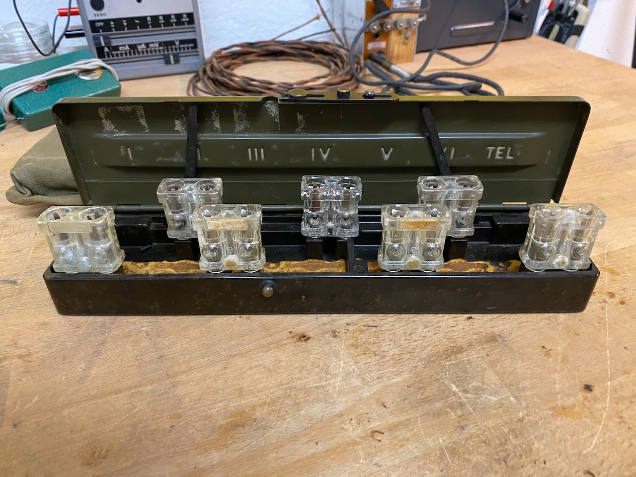
Open empty box with plugs.

Plugs in storage position.

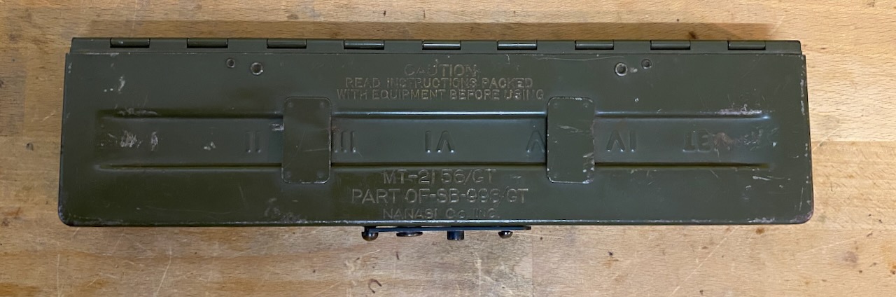
MT-2156/GT part of SB-993/GT, made by Nanasi Co. Inc (~1968).
(A "Nanasi Co. Inc." from West New York had some army contracts for telephone and telegraph equipment in the late 60ies.
There is also a "Nanasi Co. Inc." from West New York which deals in Jewelries, maybe the same company which did some War Dogs type business?)
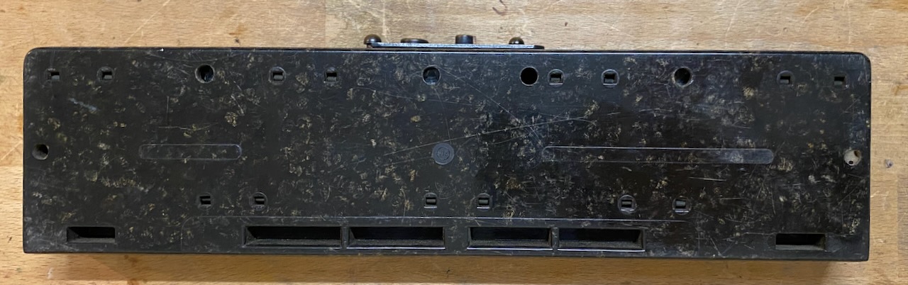
Bottom is bakelite type material.
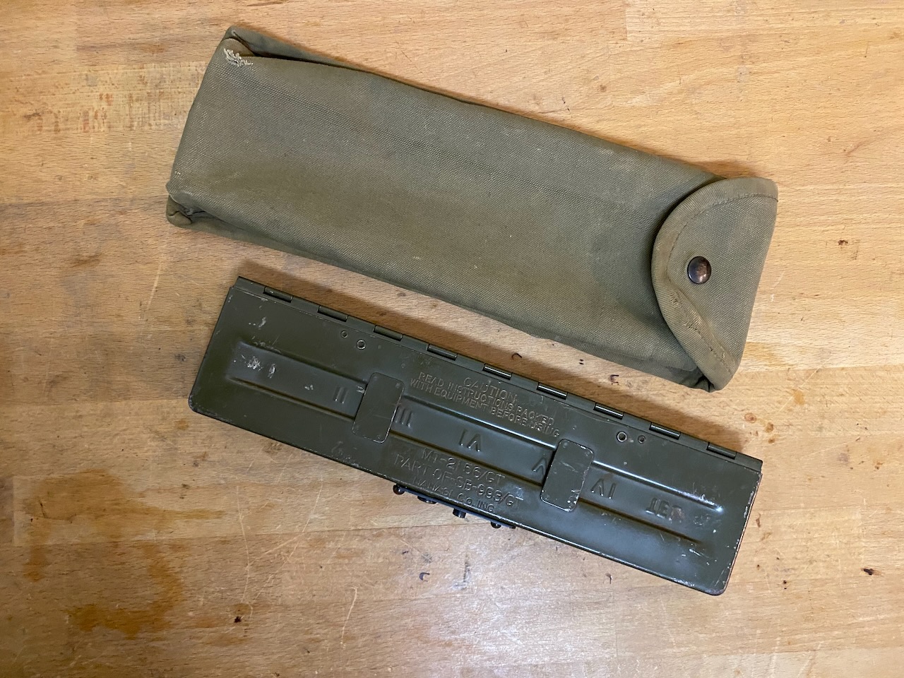
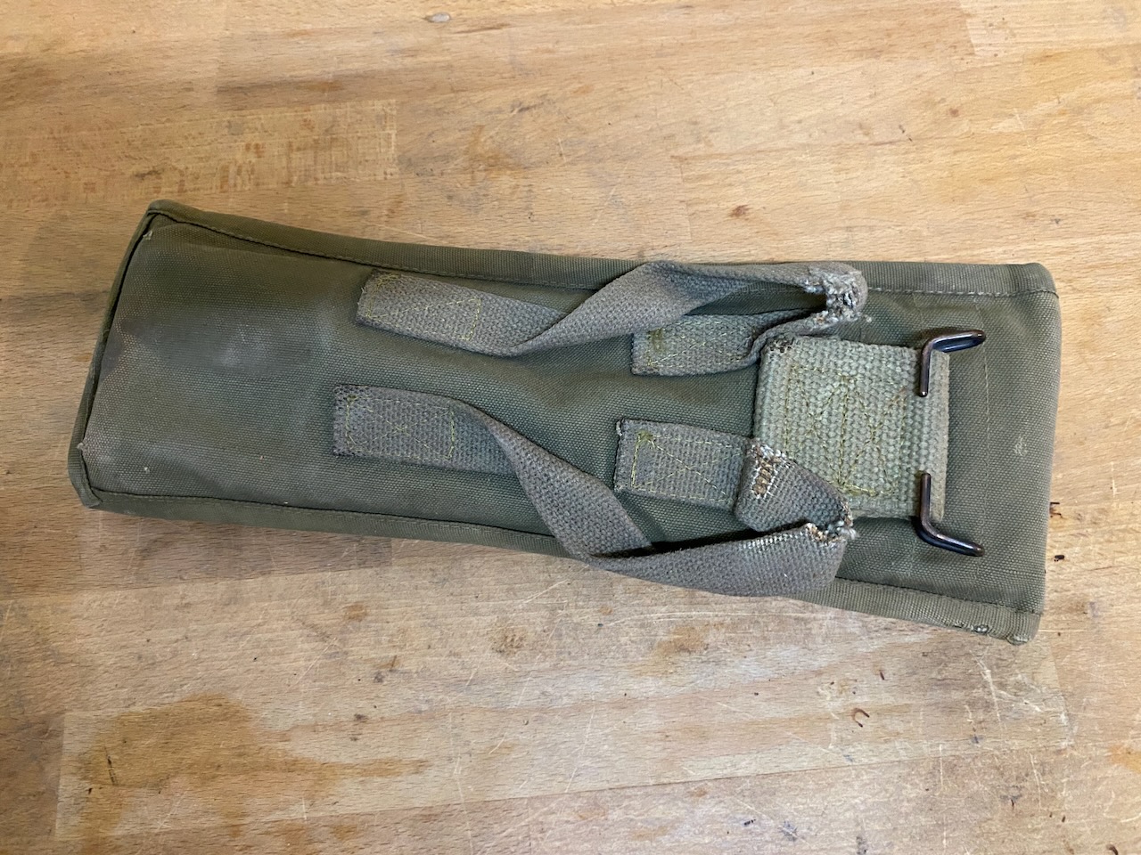
With canvas cover.
Inside cover.

Cover back with straps and hook.
SB-18/GT images provided by a Ezesar, a field telephone collector from Spain.
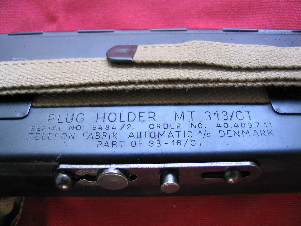
MT-313/GT plug holder with U-4/GT plugs.
Plugs stored.
The plugs are made by "S.C." (probably Stromberg-Carlsen).
Clearly visible the luminescent material on the U-4/GT plugs.

The strap provided with the board allows to mount it by strapping it to eg. a tree.
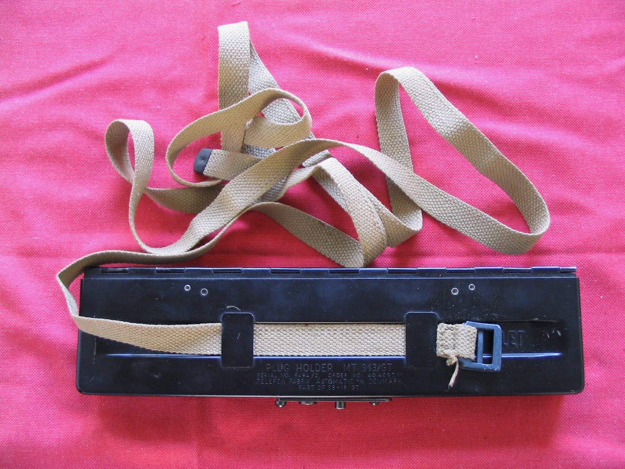
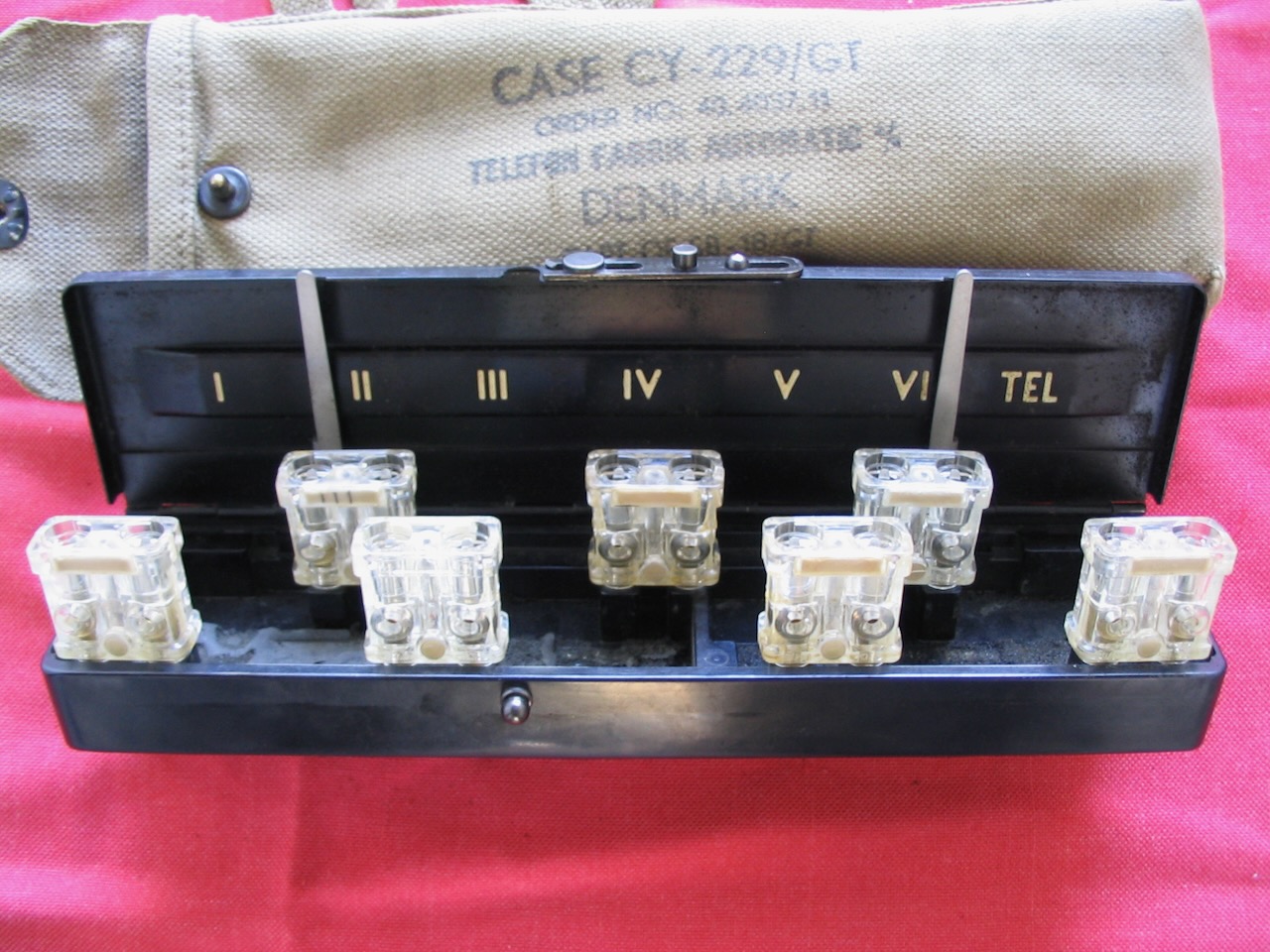
Made by Telefonfabrik Automatic A/S of Denmark.
In the canvas case.

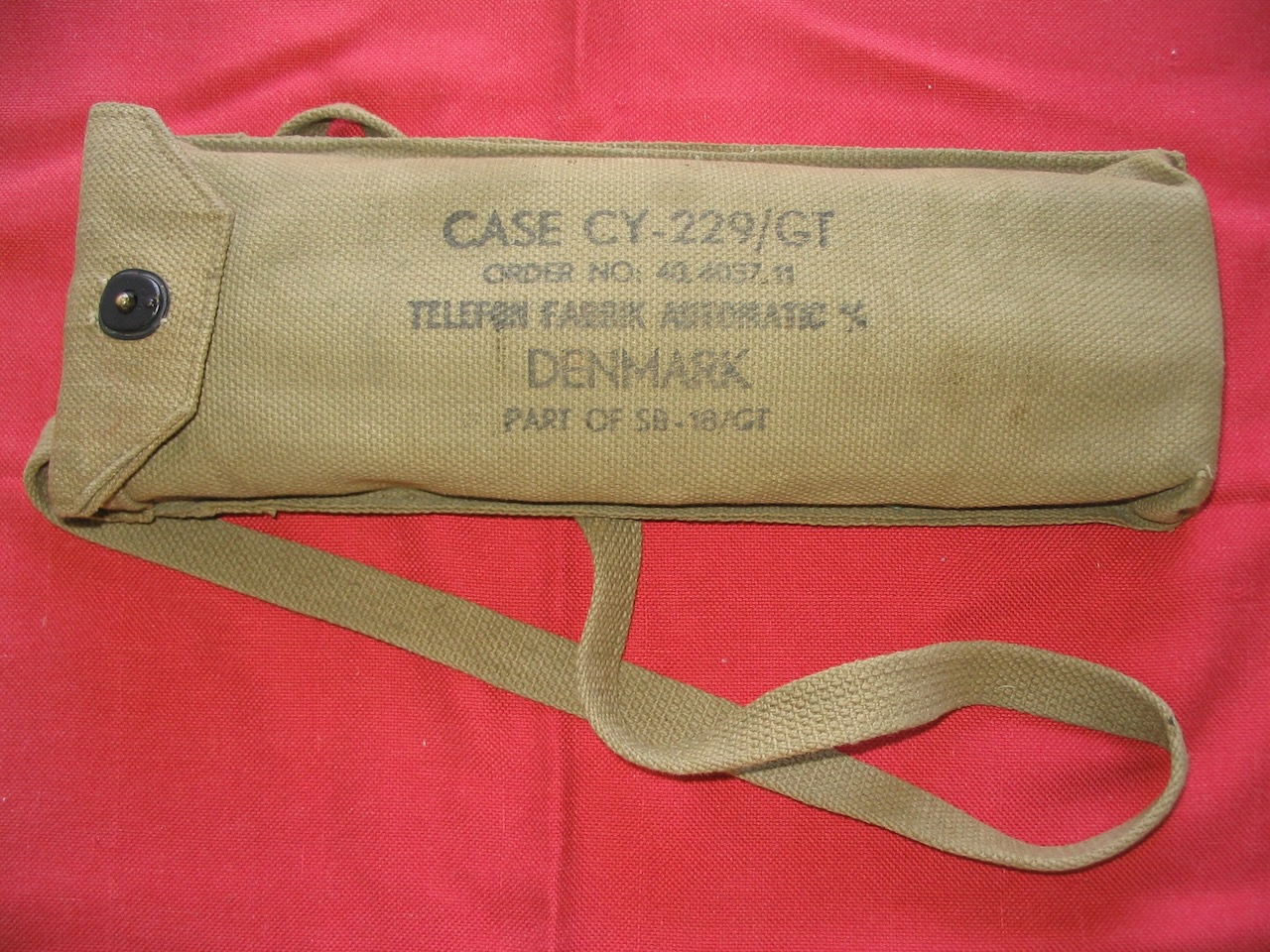
Canvas case CY-229/GT front.
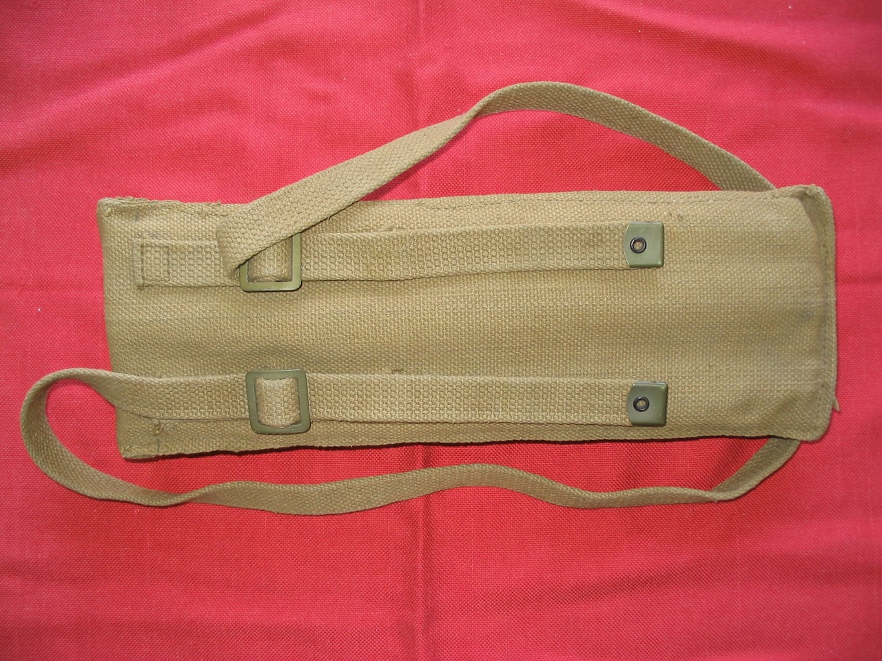
Canvas case CY-229/GT back.
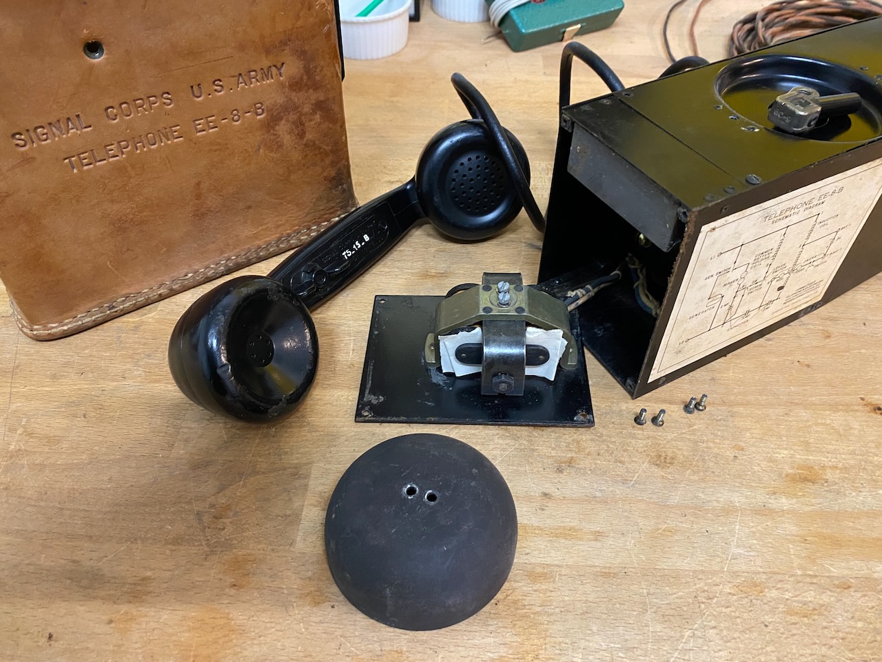
Silencing an EE-8-(*) ringer by removing the bell and blocking it with some folded paper stripes.
U-4/GT as visual ring indicator on an EE-8-(*).

Creative Commons Attribution-ShareAlike 4.0 International License