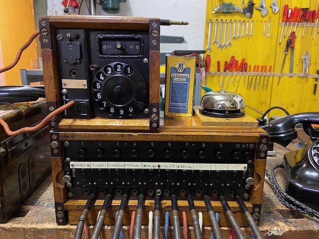
The 10 line single cord switchboard "Klappenschrank 10, OB 52" is a post WWII East German development. An improvement on the "Kleiner Klappenschrank (1933)" and compared to it a little bit smaller still and all connections on the back and user elements on the front (instead of on top), making it more "heavy duty" and stackable. It uses a form factor compatible to the "Feldvermittlung OB52/30" (a 10 line pair system) and can be used to extend their capacity to 40 lines [4] [6]. The "Amtszusatz, OB 52" (dial unit) is also compatible with the OB52/10 and the OB52/30. By the mid 60ies it was replaced by the cordless switchboard "Feldvermittlung OB-62/10" [1][2].
The switchboard uses the identical setup than the "Kleiner Klappenschrank (1933)". Per line a cord, a socket, a relay flap (with contacts for an external DC ringer) and an operator button which connects the externally attached operator field telephone to the line. There is no diagram provided on the switchboard, the electrical circuit is identical to the "Kleiner Klappenschrank (1933)" and also documented in[6].
The dial unit provides the components required for a CB/Aut. connection: holding coil, capacitor and dial. As the "Amtszusatz (1933)" the OB52 dial unit can also be used as "SB" unit (for connecting to a LB network with end of call DC supervision) [4].
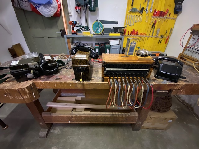
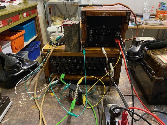
Setup for LB call demo.
FF63 on the left is connected to line 1.
FF53 is connected via patchcord and used as operator set.
The Tesla made LB telephone on the right is connected to line 2.
The Swiss Pi Zen 37 on the far right is connected to line 10.
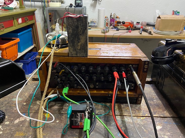
A external DC ringer (a Swiss Pi Zen 37 model) is connected together with an east german made element (only decoration, behind the switchboard a 4,5V flashlight battery has been connected to supply ringer power for the demo).
On the left the DC ringer is connected in series with a 4,5V flashlight battery to the connectors "W" (Wecker = ringer).
On the right the operator field telephone is connected with a patchcord to "Kl1" (Klinkenstecker = phone jack).
The connectors "Kl1", "Kl2" and "Abfr" (to the right of "W") are connected in parallel and can be used to daisy chain several switchboards to the same operator set.
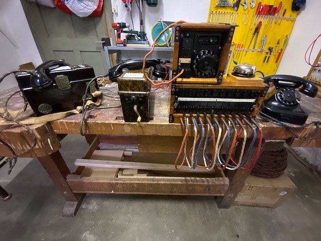
Setup for dial call demo.
TP 25 on the left is connected to line 1.
FF53 is connected via patchcord and used as operator set.
The dial unit is connected with a patchcord on the back to a switchboard operator socket and to the automatic line #19.
The east german made W38 on the right is connected to automatic line #20.
The dial unit patchcord is connected directly to the line binding posts on the back.
Use case not clear to me.
The dial unit has two parallel "Abfr" connections, either the binding posts on the left or the phone jack which we use here.
The screw head on each corner can be used to interconnect the ringer circuit between multiple OB 52 type chassis and also the dial unit (and the optional DC/AC commutator) [4].
Here connected directly in parallel to the switchboard "W" connectors.
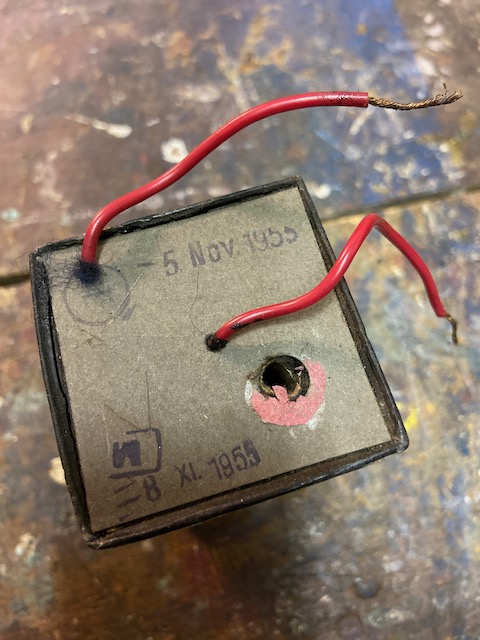
A 1,5V "Luftsauerstoff"-element made by "VEB Batteriefabrik Worbis" (later "VEB Elektrofeingerätewerk Worbis" a subsidiary of "VEB Büromaschinenwerk Sömmerda").
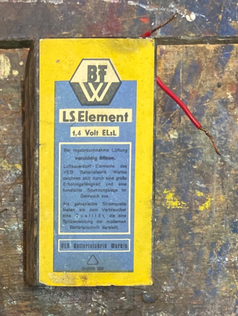
The dates on top most likely indicate the manufacturing date.
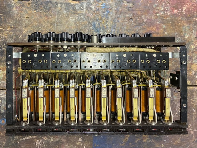
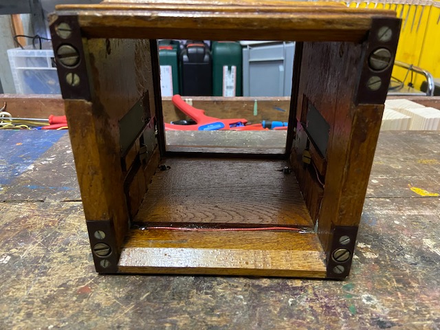
The disassembled switchboard and dial unit.
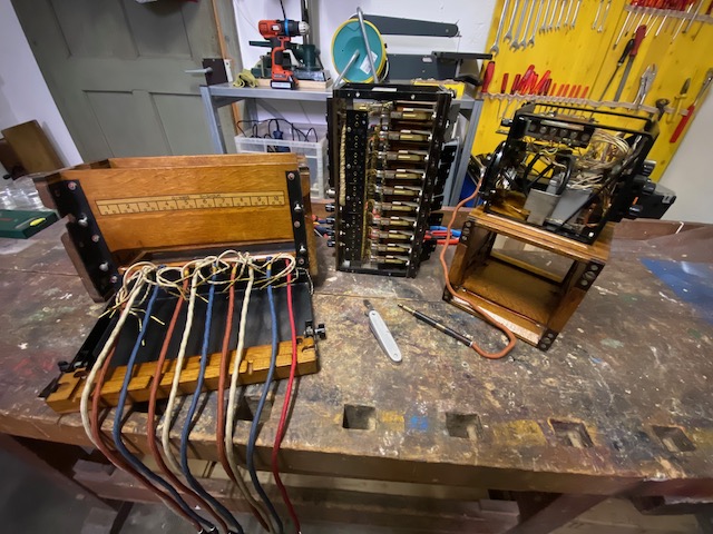
To remove the chassis from the frame the cords have to be disconnected.
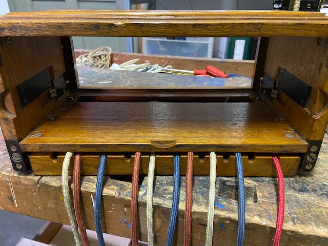
The connection tongues inside left and right connect the DC ringer circuit from the chassis to the frame and then to the corner screwheads.
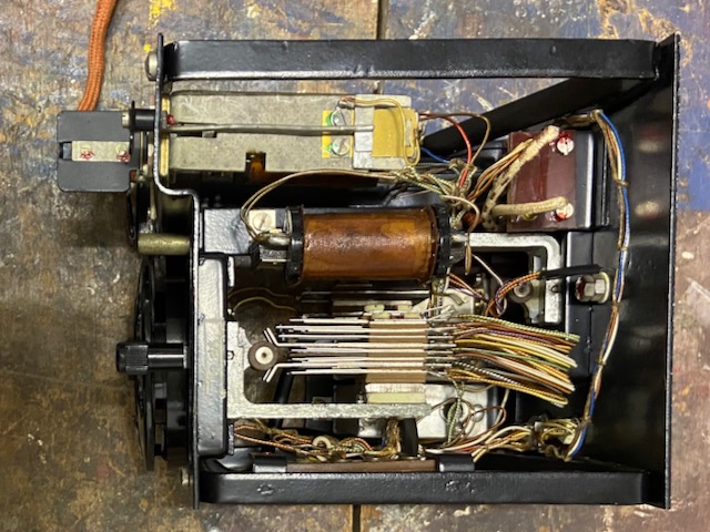
Top view.
The relays release the flap and close the DC ring circuit when actuated.
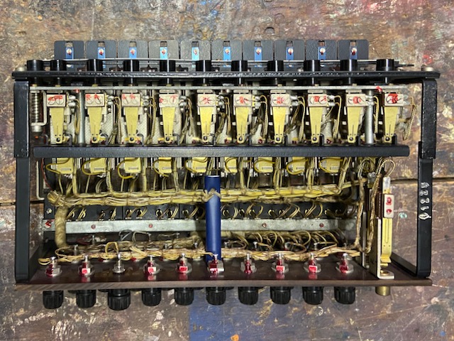
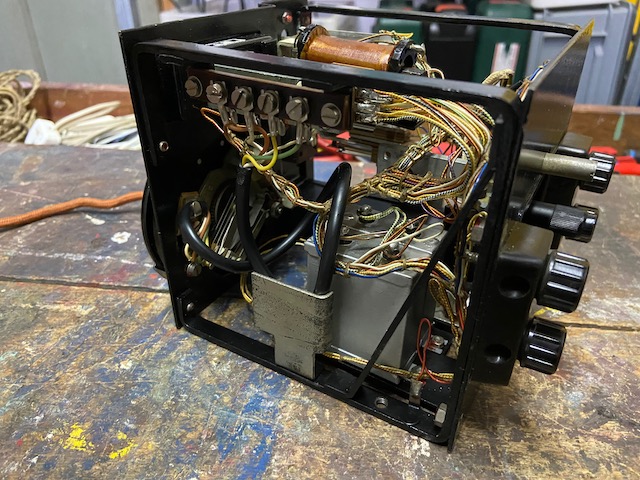
Bottom view.
The phone jacks disconnect the relay when a patchcord is plugged in.
When calling off the relay of the patch cord used will actuate, not the relay of the socket used.
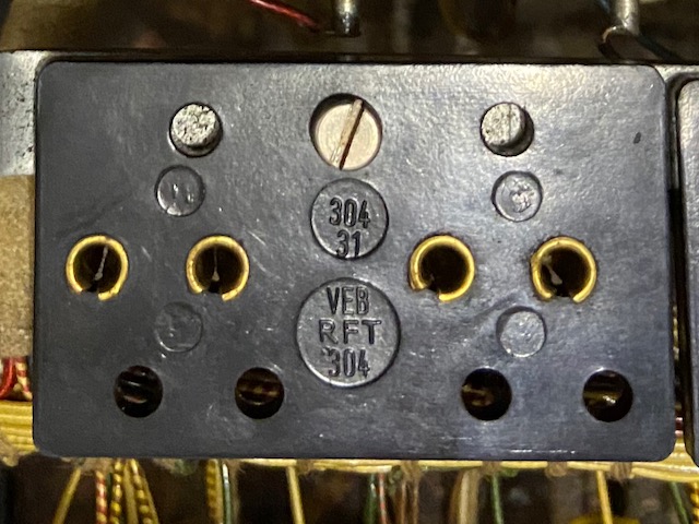
There is no mfg. label on the device.
This bakelite sockets have been made by some factory out of the RFT group.
"304" seems to indicate a factory specialised in bakelite parts, most probable it was only a sub-supplier and not the mfg. of the complete switchboard.
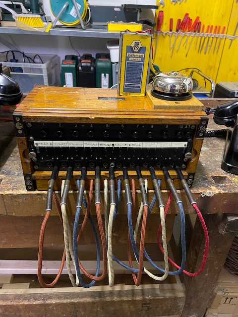
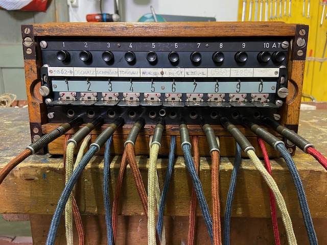
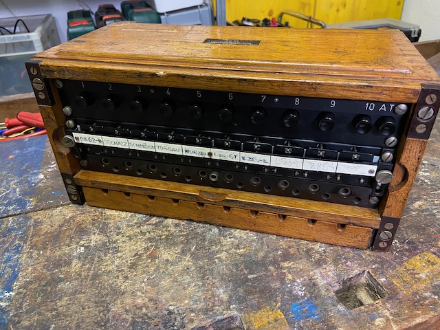
Switchboard from the front with all flaps down.
Top row: the operator switches, the far right "AT" is to reset the operator switch in use.
The flap lock bar can be fixed in the open position.
On the flap lock bar space to put a description on each line is provided.
Based on the descriptions the last active use of this switchboard was as an extension to an OB 62 in the region of North Saxony.
Behind the flaps there is a bar with the line numbers making it immediately readable which flap is down.
Bottom row: the line sockets.
For each cord there is a blind socket for storage.
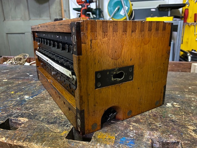
Switchboard from the back.
Line binding posts for line 1 to 10.
On the right the "Kl1" and "Kl2" sockets to connect operator field telephones, dial units and/or daisy chain several switchboards to the same operator unit.
Bottom left the "W" posts for the external DC ring circuit and the "Abfr" posts also for connecting an operator field phone (in parallel to the "Klx" sockets).
Bottom right a 30 pin connector compatible with the connector used on older equipment like the "Kleiner Klappenschrank (1933)" to connect to e.g. a "Feldkabelanschlusskasten".
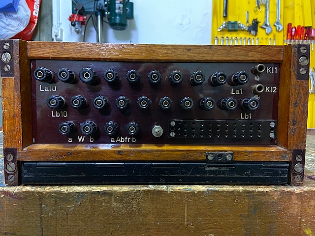
On the switchboard side a lug to connect a carrying strap.
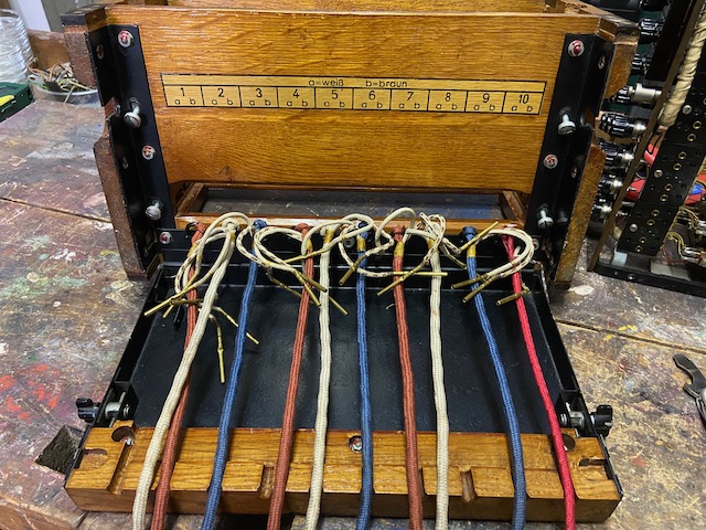
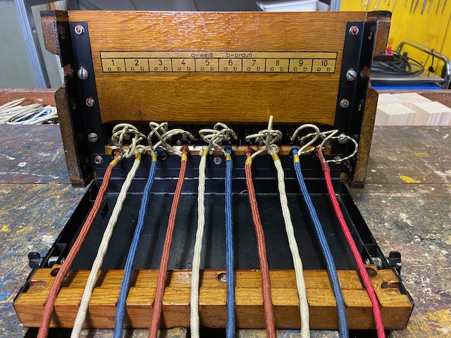
Open with cords deployed.
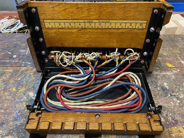
Open with cords stored.
Ready to transport (the metal lids which can be screwed on front and back are missing).
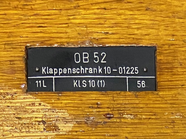
The label on top of the switchboard indicates a mfg. date of 1956.
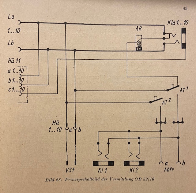
Electrical diagram from [6].
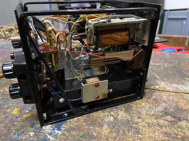
The dial unit chassis from top.
In the middle the holding coil.
From the right.
Capacitors and dial connection.
From the left.
The relay, here good visible the ring contacts at the low rear end of the relay.
At the back the patchcord connection.
The connection tongues inside left and right connect the DC ringer circuit from the chassis to the frame and then to the corner screw heads.
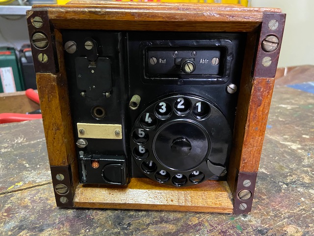
The relay flap can also be locked for transport.
Below the flap the line socket to connect a cord from the switchboard, when plugged in the holding coil is activated.
The dial unit cord is stored behind the door at the bottom left.
The dial unit cord is directly connected to the line, usage is unclear to me (also no use for it is mentioned in [6]).
To use the line the switch on the top right has to be put into "Abfr." (query) position (connects the holding coil = "off hook").
The "Ruf" (call) position is to be used when connected to an SB line (LB with DC supervision).
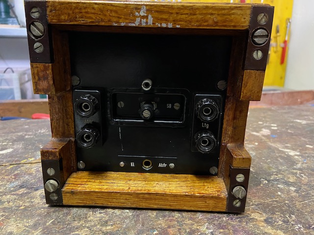
The "Abfr." binding posts and the "Kl Abfr" jack are connected in parallel and can be used to connect to a switchboard or a operator set.
The line is connected to the binding posts on the right.
the switch in the middle can be used to change the mode from "dial unit" to "SB unit", the default middle setting is "dial unit" (the switch is spring loaded self locking, to switch over it has to be pulled out).
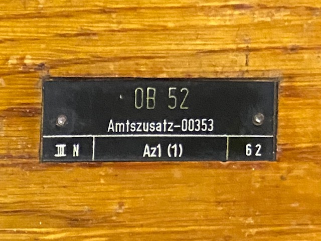
The label on top of the dial unit indicates a mfg. date of 1962.
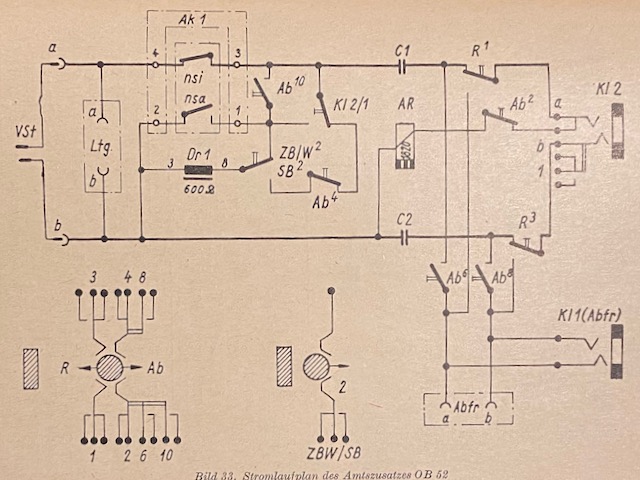
Electrical diagram from [6].
Creative Commons Attribution-ShareAlike 4.0 International License