The Pionierzentrale Modell 37 was the first Swiss developed field switchboard. It was the successor of the Pionierzentrale Modell 18 which was the Swiss Army Name for the German Feldklappenschrank neuer Art from 1915. Developed and manufactured by Albiswerk Zürich (The Swiss Siemens & Halske subsidiary). It was acquired in two lots, the first 548 from 1937 to 1942 and a second batch of 125 in 1950/51 (Toal 673). The one used for the Videos and Fotos here is from 1938 with serial #91. (Last "active duty" for this specific one was stored at the Swiss national radio and TV station to be able to integrate into military emergency communications in case of a crisis situation). The Pi Zen 37 was used by the army up to at least the early seventies.
The Pi Zen 37 is a cord pair based 10 line switchboard. Each line can be connected to a single-wire or double-wire LB setup, and also support CB or Automatic connections. Each cord pair includes a transformer completely galvanically separating the lines, allowing to make connections between any two different types of connections. The relay flaps included in each of the ten line (yellow flaps) and five cord pair (red-white flaps) modules are highly sensitive and act on magneto or buzzing signals. The flaps can be reset by small levers. The line flaps are also automatically reset when plugging a cord. The switchboard is modular built, line and cord pair modules can be replaced independently. The cord pairs are stored in a built in bottom compartment.
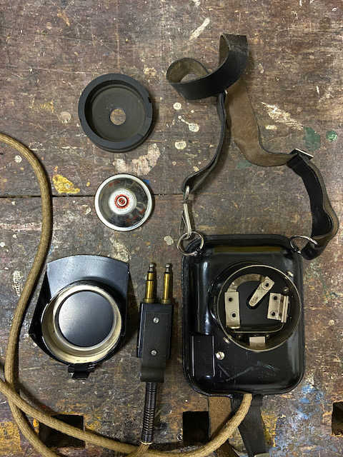
The built in operator set is based on the A.Tf. 32 field telephone set using the same buzzer/induction coil combined setup and the same magneto with foldable magneto handle. To operate either a bakelite handset from an A.Tf. 32 (in case of "low traffic") or the included chest microphone and headset fitting can be used. For incoming signalling the operator can choose to only work with the visual call indicators or with an included buzzer ringer or an external optional DC bell ringer (provided in the accessory drawer). For outgoing signalling either the included buzzer or magneto can be used or an optional external 70V 50Hz AC Source can be connected.
The switchboard requires two 3V DC sources, one for the microphpne and buzzer, the other for the included buzzer ringer or external DC bell ringer. These batteries can either be provided by 2x 2x1,5V dry elements (Same as used in swiss field telephones of that era, size IEC S4) mounted in the external battery box and connected by a special included battery box connection cable (connector can be put in both ways for an easy change to the better battery for the microphone) or other external 3V batteries can be connected to battery terminals on the top.
All connection terminals are on the switchboard top (not protected by any lid, according to certain manuals it seems that the switchboards were sometimes stored and transported in an additional outer wood box but I've never seen one). Apart from the ten terminal pairs for the lines there are 5 pairs to attach either local telephones or to connect other switchboards for a multiple type setup. Then there are the already mentioned battery terminals, terminals for an external 70V AC ring current source, terminals for the external DC bell ringer and an earth terminal.
In case just two three lines more than ten are required the switchboard provides latches on the right side to extend it with one or more Vermittlungskästchen.
The accessory drawer holds the chest microphone and headset fitting, the external DC bell ringer, a length of earth wire and a screwdriver.
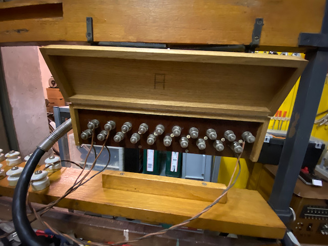
The switchboard can be used together with a line entry set consisting of a frame to connect the outside lines, a special combined 10 line cable which is passed to the indoor/in tent side and a ten line lightning arrestor box to which then the switchboard is connected. The line entry frame can also be used to mount a Vermittlungskästchen based switchboard or to mount a Pi Zen 37 directly onto it if no table or other support is available. This uses will be presented in a future episode.
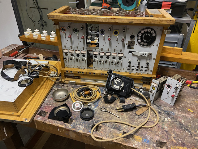
Disassembled.
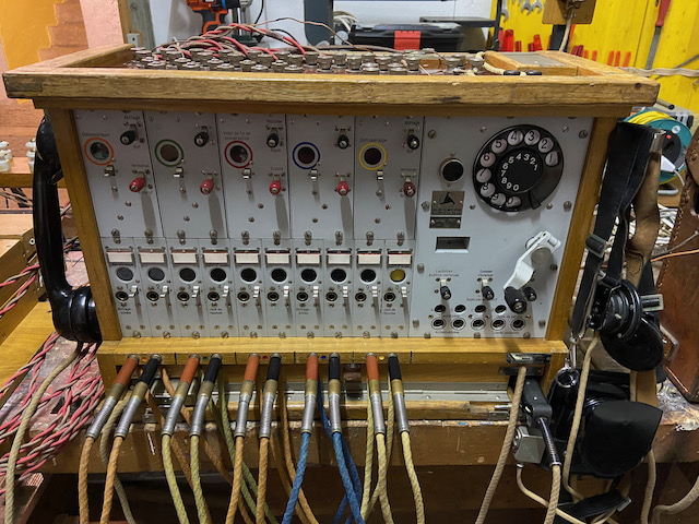
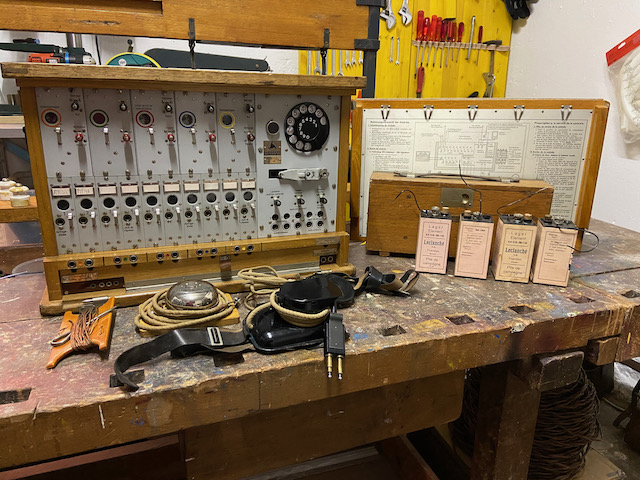
Ready to use.
Installation & user guide (Mounted to inside of front door).
In german and french.
(Click image for large version)
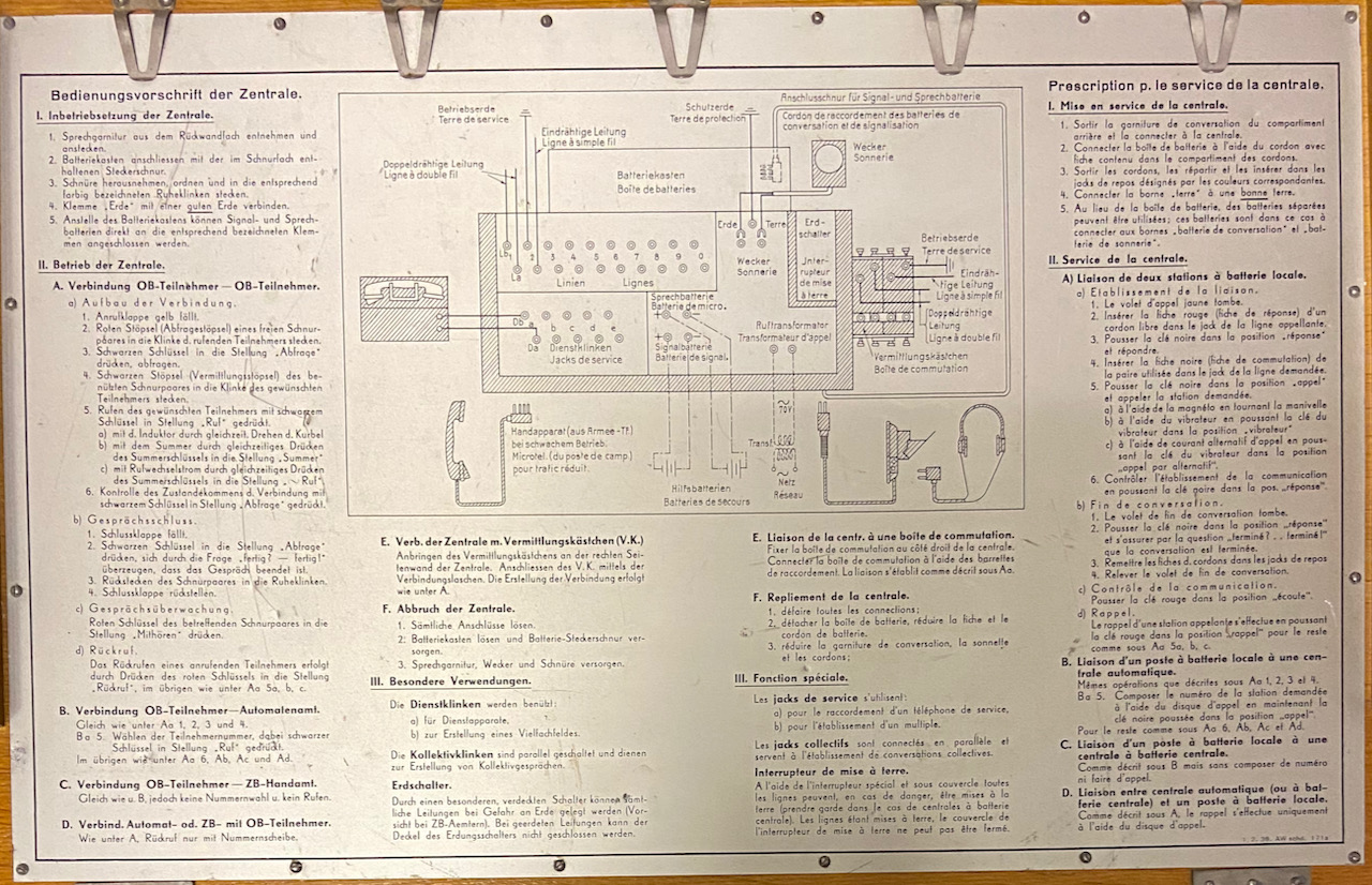
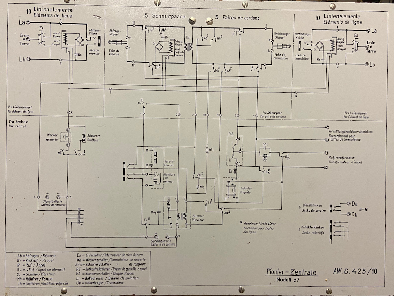
Diagram (mounted to inside of back door).
(Click image for large version)
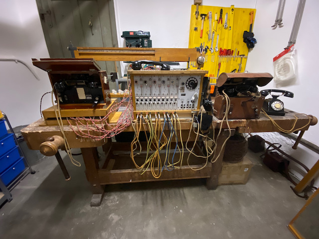
The setup used in the videos.
In the background the entry frame.
On the left the A.Tf. 32 connected to switchboard line 1.
Below that the ten line lightning arrestor set.
On the right the F.Tf. 41 connected to switchboard line 2.
And on the far right a PTT Modell 29 connected to PBX line 20, switchboard line 0 connected to same PBX line 19.
The same setup from above.
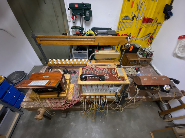
The "outside" end of the line entry cable.
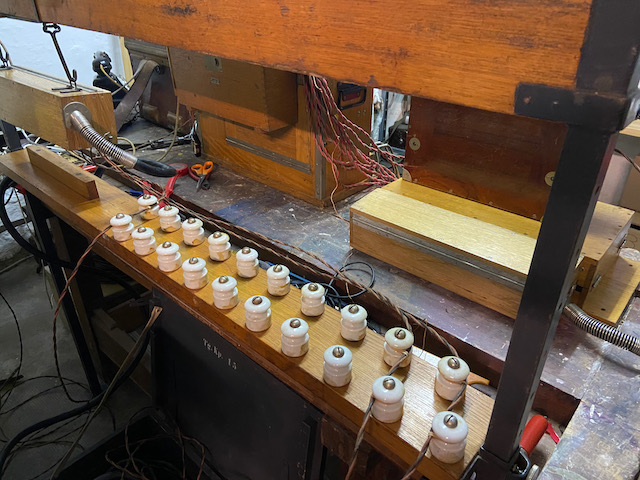
The "inside" end of the line entry cable connected to the lightning arrestor box.
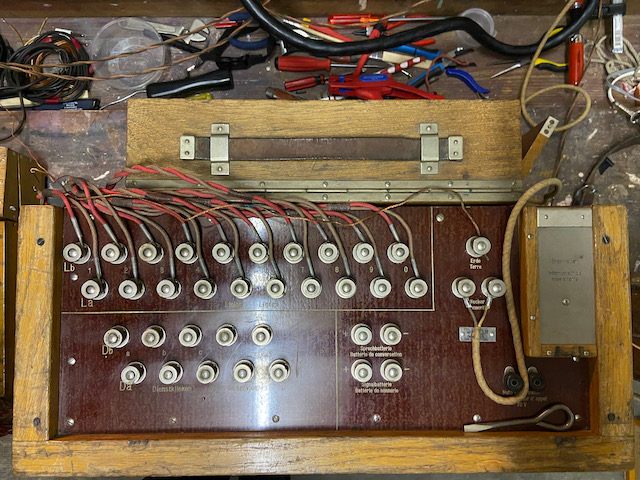
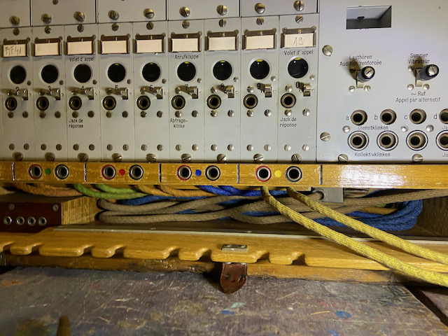
Connections on top of switchboard.
The five front terminal pairs a to e are to form a "multiple" with other switchboards.
Earth and external DC bell ringer are also attached.
Then there are terminals for external batteries and for an external 70V AC source to use as ring signal generator (instead of the built in manual magneto).
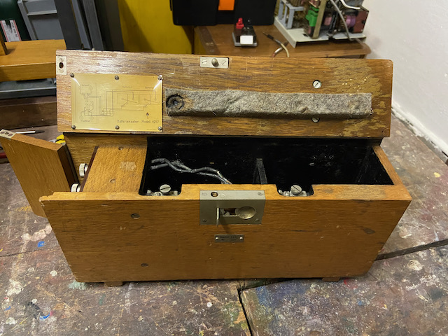
The battery box (empty).
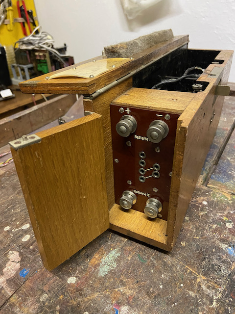
The battery box panel.
The battery plug is connected to the center four pole socket.
(The two pole sockets could be used with the old Pi Zen 18).
The terminals allows other use of battery box without any plug (e.g. if the built in cable is defect).
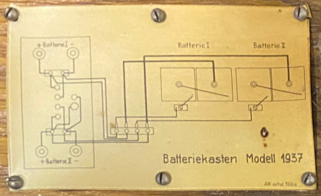
Battery box diagram.
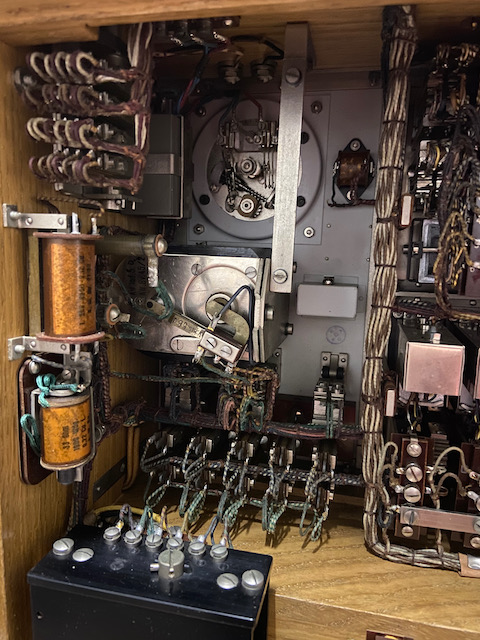
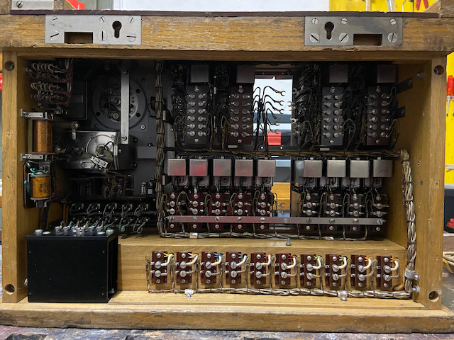
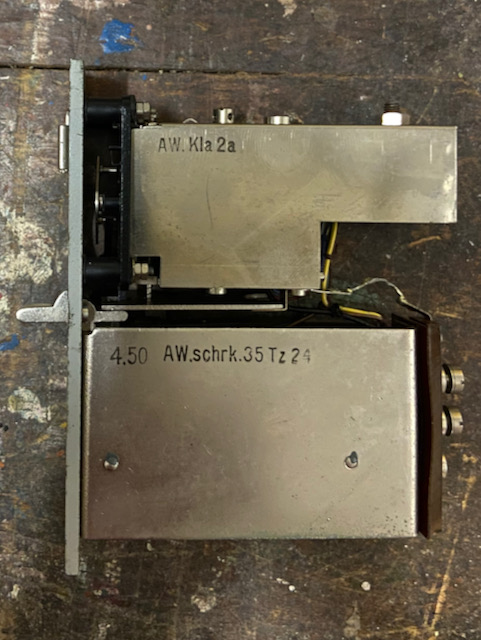
Open switchboard.
The operator set side.
Magneto, capacitor and buzzer ("Albissummer", black box bottom left) identical to A.Tf. 32.
The resistance (in front of the magneto) is connected when listening into the line (with red key).
The coil in fron of that is used when buzzing to pass some of the buzzer current through the local RX for control.
Below that the ringer buzzer indicating incoming calls (when switched on).
Also visible are the back of the dial and to the left the back of the indicator for magneto and dial control.
In the topmost row the five switching modules (middle one removed).
In the second row the ten line modules (line 5 removed).
In the bottom row the cord pair connections.
The switching module from the left with the transformer and above (covered) the relay flap.
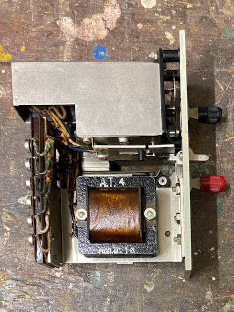
The switching module right side with the black (query and call) and red (listen in and call back) key switch and the capacitor.
This module is assumed to be in the switchboard since initial built time being from 1938.
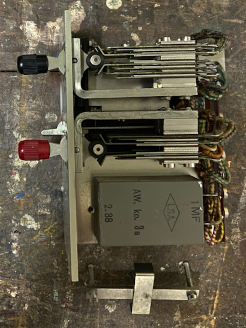
The line module from the left with the capacitor and the line plug and above the (covered) the relay flap.
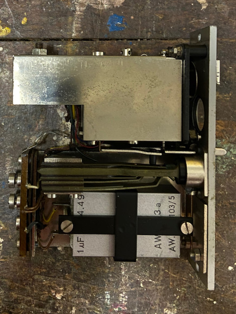
The line module from the right.
This line module seems to have been replaced sometime as the mfg. date is from 1950.
The chest microphone with cap removed.
TX module is of type 1946 and mfg. in 1969.
The headset bears a Siemens & Halske logo (Albiswerk Zürich was after all the Swiss Siemens subsidiary).
The code ZT7 indicates a year of make of 1938 (T is the datecode for 1938)
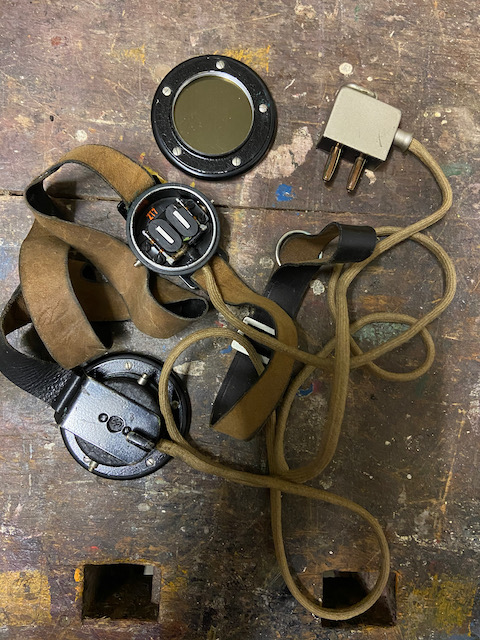
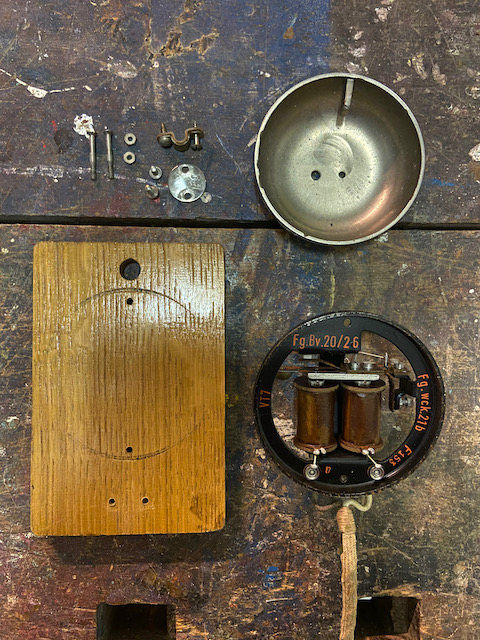
The external DC bell ringer is also a Siemens & Halske product based on the mfg. codes (as Albiswerk codes seem to have always started with AW.).
Also with a datecode corresponding to 1938.
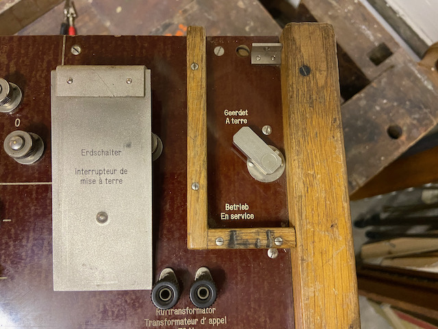
With the earth switch all lines can be shortened to earth (e.g. in case of electrical storm)
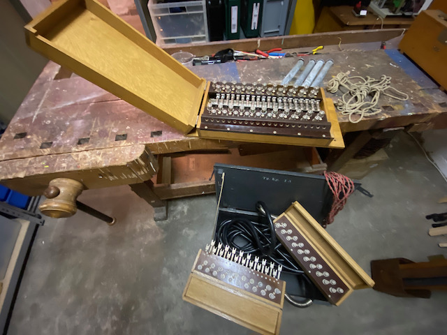
Ready to pack.
The accessories in front can be packed into the drawer in the back.
The door in the background is mounted to the switchboard front as cover.
Earth wire, screwdriver, bell and chest-/headset stored.
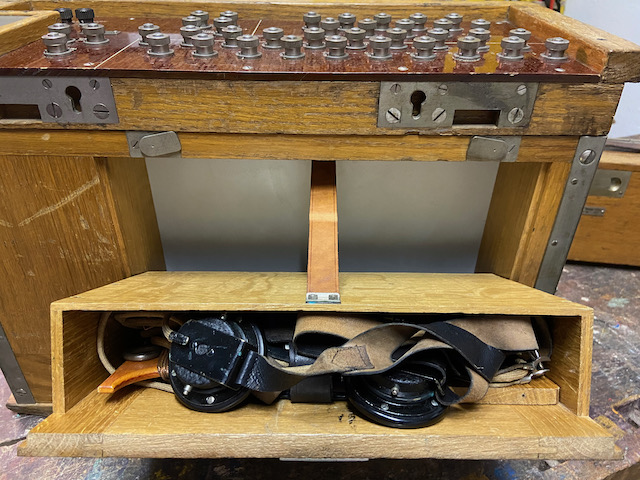
The cord pairs are stored in the compartment below the switchboard.
The line entry set and it's accessories are stored in a wood box.
All stored and ready for transport.
The line entry frame is packed together with a leather cover.
![]()
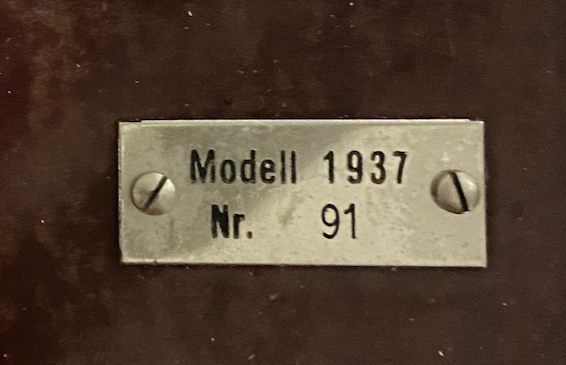
Serial number 91.
Creative Commons Attribution-ShareAlike 4.0 International License