Fullerphones are British DC telegraphy instruments named after it's inventor A.C. Fuller. Traditional telegraphy, buzzer telegraphy and voice communication were suspect to interception, especially during WWI trench warfare where lines of the different belligerents were constructed very near to each other. The Fullerphone solved this by using very faint DC currents (<2.5uA) with flattened signal edges to prevent any overhear-able induction. To make the signals readable by the operator these faint DC currents were converted into audible buzzing signals (~550Hz) by use of an adapted buzzer gadget. Fullerphones were still used into WWII.
Wireless for the warrior provides excellent technical and historical information about British Fullerphones and similar devices from other countries.
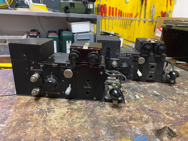
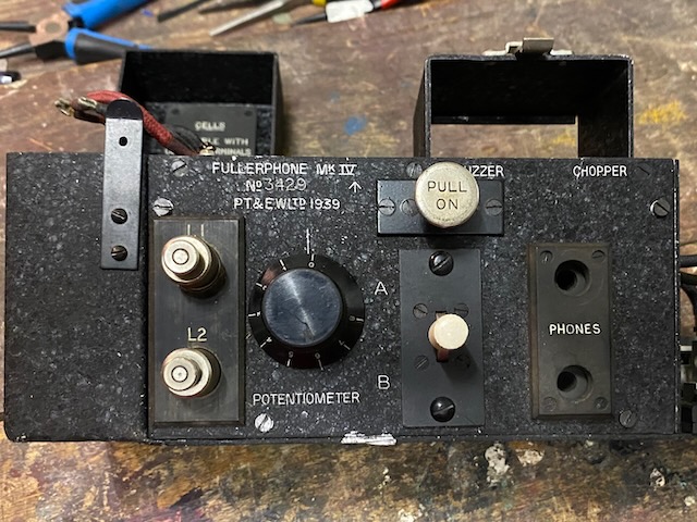
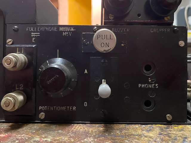
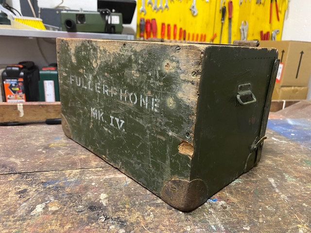
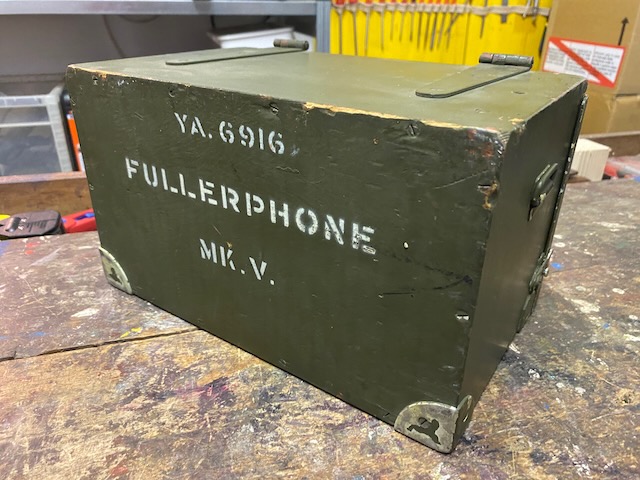
The presented Fullerphone Mk. IV is, as the name indicates, a fourth generation device developed in the mid 1930ies. This one was made in 1939 by P.T. & E.W. Ltd.. In the gallery below we present also a Fullerphone Mk. V made in 1944. The main differences between Mk. IV and Mk. V are the use of additional R/C circuitry for radio interference suppression and a crash limiter parallel to the headphones plug.
General description (abridged) from [1]:
Purpose and facilities: The Fullerphone Mk. IV is a portable D.C. telegraph instrument of high sensitivity. It is suitable for use in forward areas as its signals are practically immune from interception. The instrument can be superposed on existing telephone systems when telegraph communication is required between points served by such systems.
Range of working: Since the instrument is essentially direct current operated and uses morse signalling only, range is only limited by the leakage and resistance of the line and by interference from stray earth currents. The instrument will produce a readable signal with a current of only 0.5 microampere flowing, so that very high resistance lines may be used in emergency conditions.
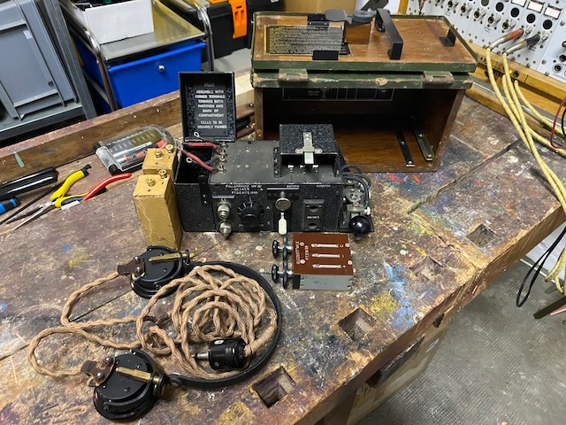
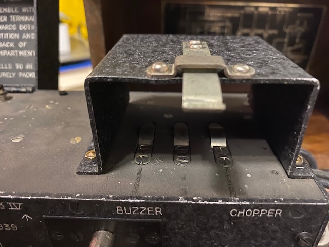
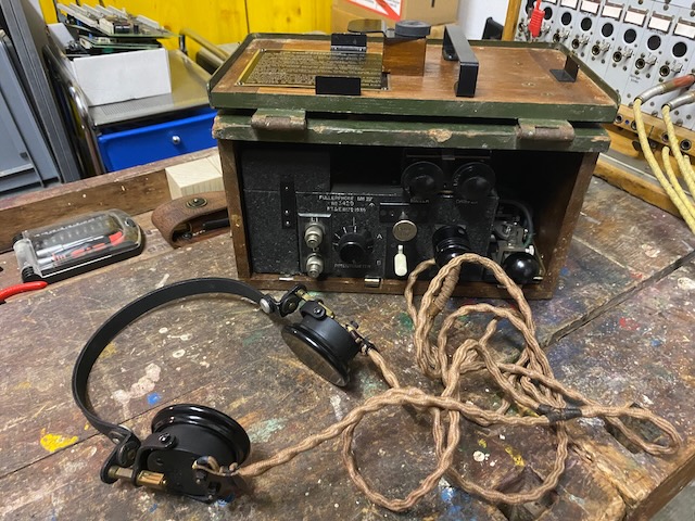
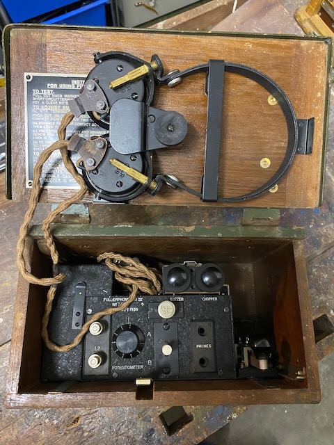
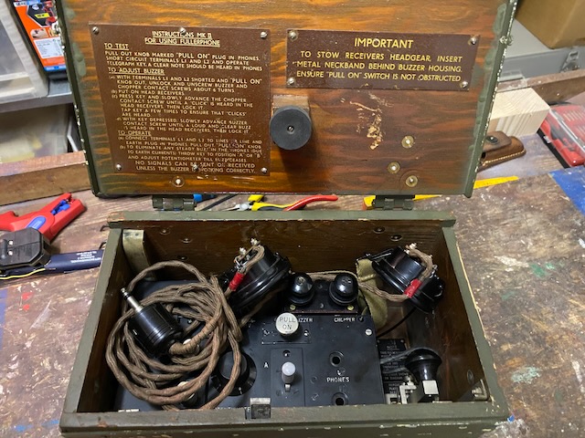
Constructional details: The Fullerphone is housed in an aluminium case which, in turn, slides on guides in a wooden carrying case provided with a sling. The headphones are held in the lid of the carrying case. A spring stop which holds the unit in position in the carrying case is pressed down for the unit to be drawn forward into the operating position. When in the operating position, the outer case gives some measure of protection to the instrument when working in bad weather. The buzzer-chopper (Buzzers F, Mk. II) unit slides into position on the top right-hand side of the instrument, the connections being made by contact springs. The morse key is mounted at the bottom right-hand side of the unit. All the other components are contained in the aluminium case. The instrument control panel is of aluminium and carries the line terminals L1 and L2, potentiometer control knob, reversing switch (marked A–B), "PULL-ON" switch and two " PHONE " sockets.
Earlier British Fullerphones included voice telephony functionality in the same instrument (probably that is why they still were called Fuller-phones and not -telegraphs). But from Mk. IV onwards Fullerphones were either operated "online", meaning an operator was always on duty and listening (like on wireless stations) or had to be combined with a field telephone which provided call signalling functionality.
Fullerphone Mk. IV disassembled.
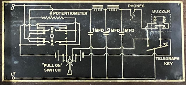
Electrical diagram Mk. IV.
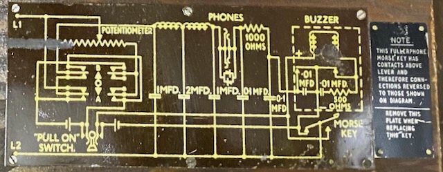
Electrical diagram Mk. V (Additional R/C circuits and a crash limiter).
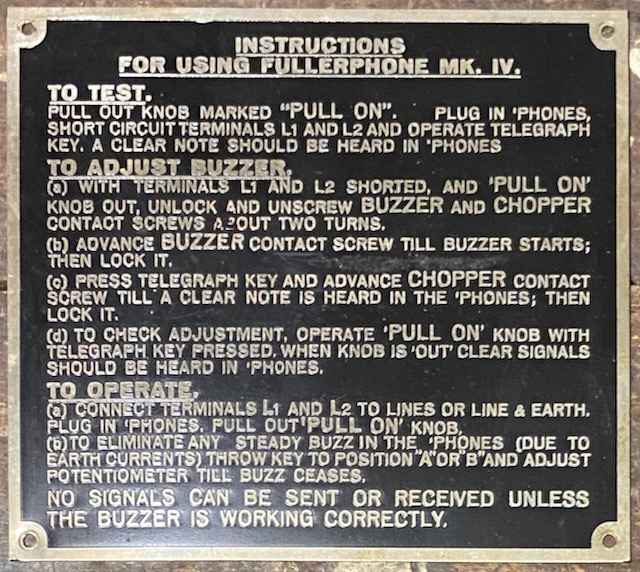
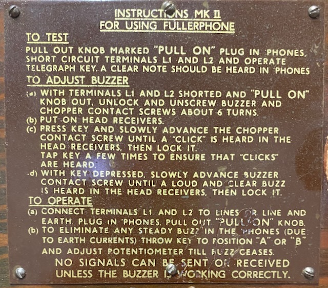
User guide Mk. IV.
User guide Mk. V (Buzzer adjustment sequence changed).
Mk. V. (Mk. IV* modified to Mk. V.) in front, Mk. IV in the back.
No company or year indication on the Mk. V., the capacitors inside have mfg. date of 1944.
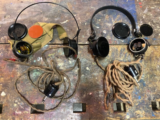
On the left Mk. V. headgear, on the right Mk. IV. headgear.
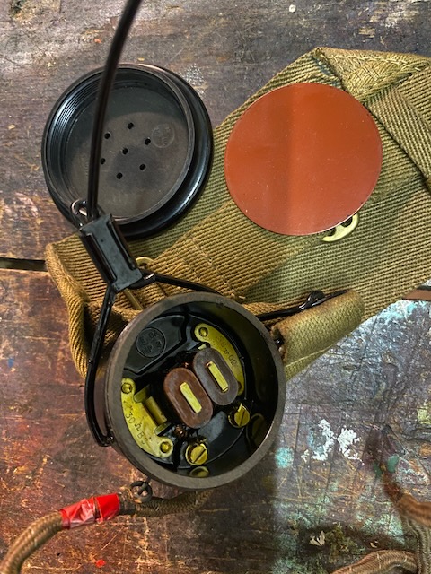
Mk. IV. headgear (C.L.R. double Mk III).
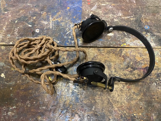
Made in 1939, type C-LR (I assume LR = "low resistance", 2* 30Ohm).
Broad arrow marking.

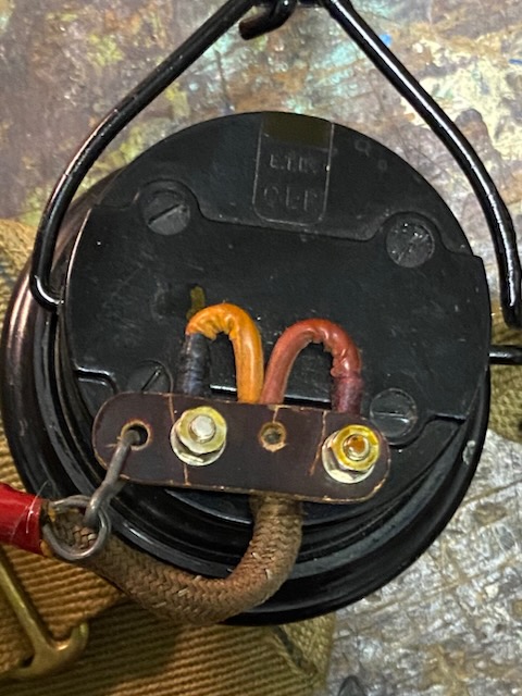
Mk. V. headgear receiver open, 30Ohm marking visible.
Mk. V. headgear receiver back.
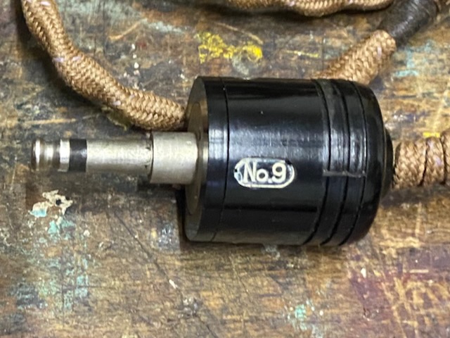
Plug No. 9, Mk. IV.
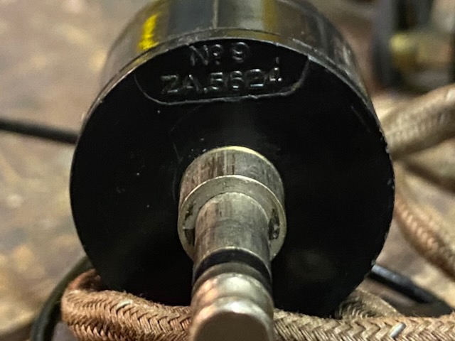
Plug No. 9, Mk. V.
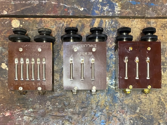
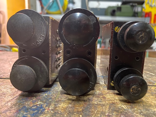
Three different buzzers.
From left to right:
T. Mk. I., 5 contacts, field telephones buzzer (eg. used in F.Mk.I/II, D.Mk.V. or Switchboard U.C. 10),
F. Mk. II., 3 contacts, buzzer used on Fullerphone Mk. IV.,
F. Mk. II*, buzzer used on Fullerphone Mk. V.
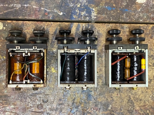
Buzzers open (same sequence than above).
Note the added resistance and capacitors in F. Mk. II* (far right).
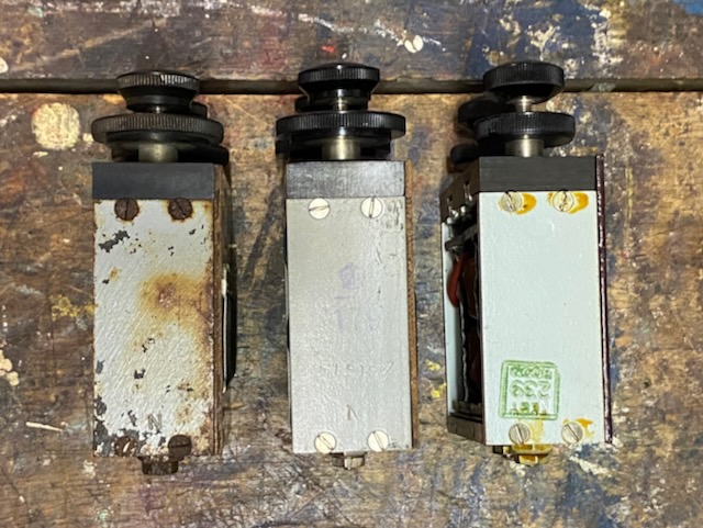
Buzzers right side.
Buzzers bottom.
.jpeg)
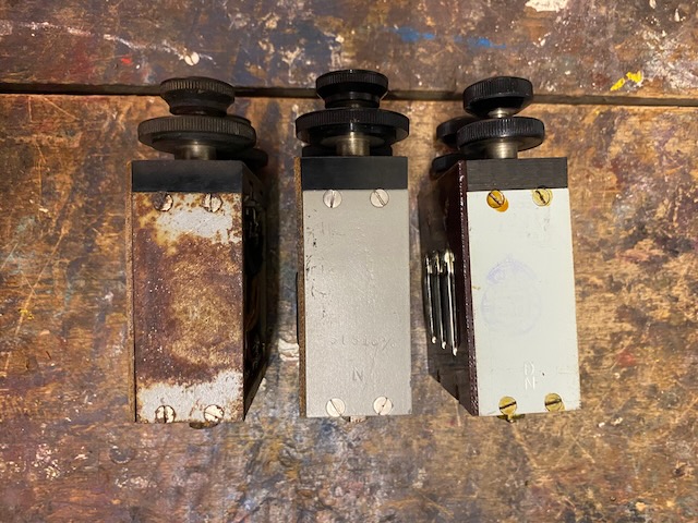
Buzzers left side.
Buzzers top.
F. Mk. II* has adjusting screws with "overturn" protection.
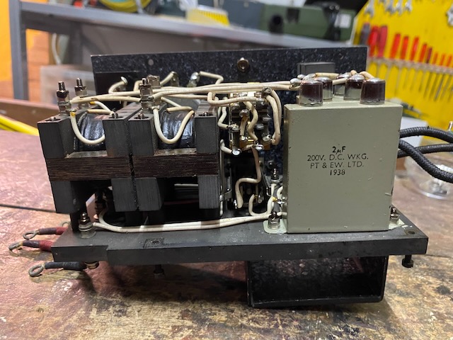
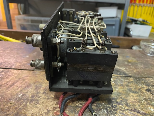
Mk. IV. inside back view.
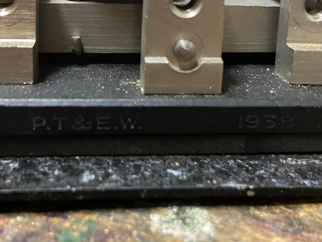
Capacitors made by P.T. & E.W., 1938.
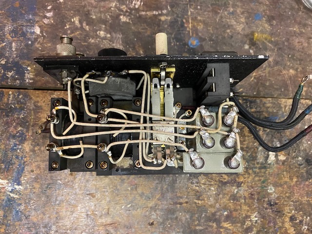
Mk. IV. inside bottom view.
Mk. IV. inside key connection side view.
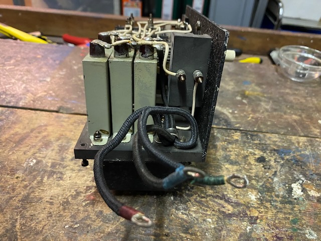
Mk. IV. inside battery connection side view.
Buzzer slide in compartment.
Mk. IV. empty shell.
![]()
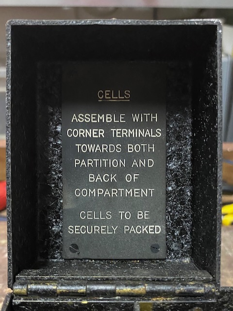
Mk. IV. battery mounting guide.
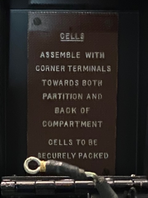
Mk. V. battery mounting guide.
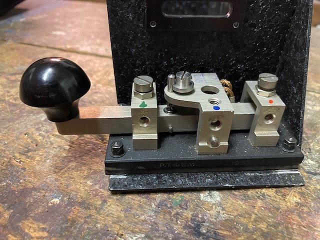
Mk. IV. key (disconnected, color coded).
Mk. V. key.
Mk. IV. key made by P.T. & E.W., 1938.
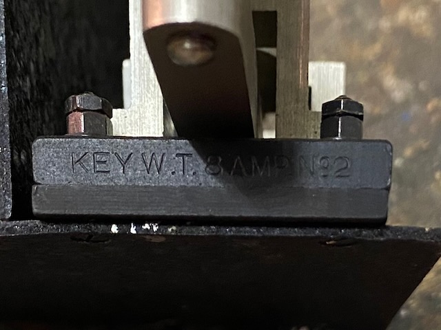
Mk. IV. Key W.T. 8AMP No. 2.
(W.T. 8AMP key seem to be one of the most ubiquitous morse keys, made in 100 variations and in the millions [3] [4])
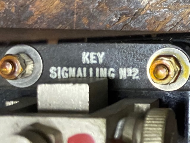
Mk. V. Key Signalling No. 2.
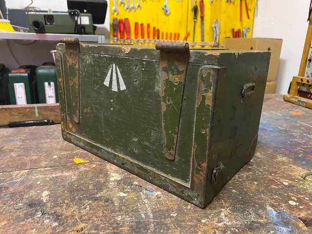
Mk. IV. empty box, with headgear brackets in lid.
![]()
Mk. V. empty box.
![]()
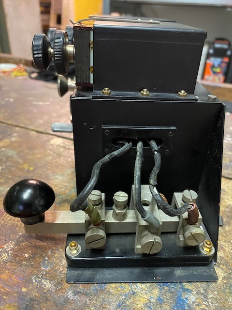
Mk. IV. front.
The potentiometer and A-B switch is used to compensate interfering earth currents.
Mk. V. front.
(It is a modified Mk. IV.*)
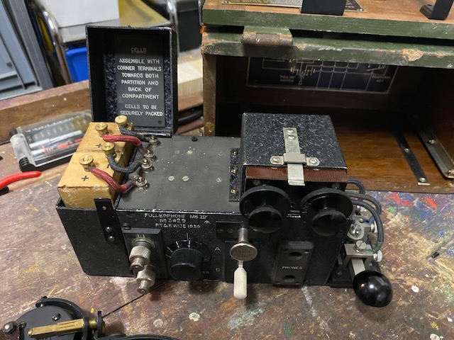
Mk. IV prepared to use with batteries connected.
Mk. IV. ready for use.
Mk. IV. ready to store.
Headgear stored in lid.
The center rubber puck on the lid presses on the "Pull On" switch and switches off the instrument when lid closed.
Mk. V. ready to store.
Headgear stored inside box.
The center rubber puck on the lid presses on the "Pull On" switch and switches off the instrument when lid closed.
Mk. IV. box front with broad arrow.
Mk. V. box front.
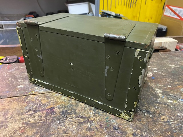
Mk. IV. box front back.
Mk. V. box front back.
The setup used for the demo in the video above.
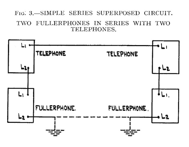
Two Fullerphones and two Telephone sets D. Mk. V. connected as simple series superposed circuit.
The blue cords represent the wireline on which the "Vermittlerkästchen 38" simulates an eavesdropper.
The yellow cord simulates the earth connection.
The voltmeters are connected to the headphones to visualise the generated tone.
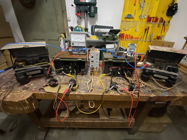
Two Fullerphones and two Telephone sets connected as simple series superposed circuit using a single wire and earth setup.
Diagram from [1].
Creative Commons Attribution-ShareAlike 4.0 International License