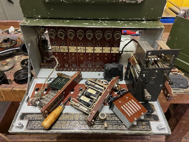
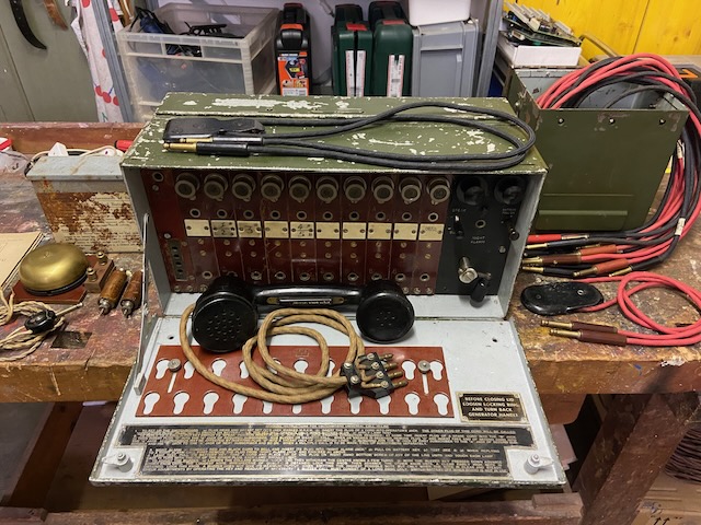
A British field switchboard from the 1940ies. U.C. stands for "universal call", as it supports incoming and outgoing buzzer (~350Hz) and magneto (~20Hz) signalling. There was also a slightly smaller but otherwise nearly identical 6 line version.
The Switchboard U.C. 10-Line and the Switchboard U.C. 6-Line are portable telephone switchboards for army use accommodating 10 lines and 6 lines respectively. Apart form their use in locality offices, the 10-line switchboard is suitable for use in divisional signals and the 6-line switchboard for battalion and artillery regiments. The equipment has been designed for mobile operations and can be set up and dismantled easily and quickly. The switchboards respond to and are provided with magneto generator and buzzer calling. The 10-line switchboard is arranged so that telegraphy or telephony may be superposed on three lines, while the 6-line switchboard has facilities for superposing on one line only. The superposing is carried out by means of additional apparatus which may be attached to the switchboards. Both switchboards are similar in construction and circuit details and are built on the unit principle, each comprising line units, common apparatus unit and operator's unit. One line unit is used for each line and the assembly associated with any line may be removed for adjustment and repair without disturbing other line circuits. Lamps are provided on the line units for use as calling and clearing indicators. The common apparatus unit includes a magneto generator and buzzer for calling purposes. The operator's telephone circuit on both instruments incorporates an anti-side-tone circuit which supresses sidetone to a low level. The operator is protected from acoustic shock, due to key clicks or other forms of transient interference, by a "crash limiter". A night alarm is provided, which may be used during quit periods, so that when a subscriber on any line calls the exchange, a bell rings, in addition to the lighting of the indicator lamp of the particular line.
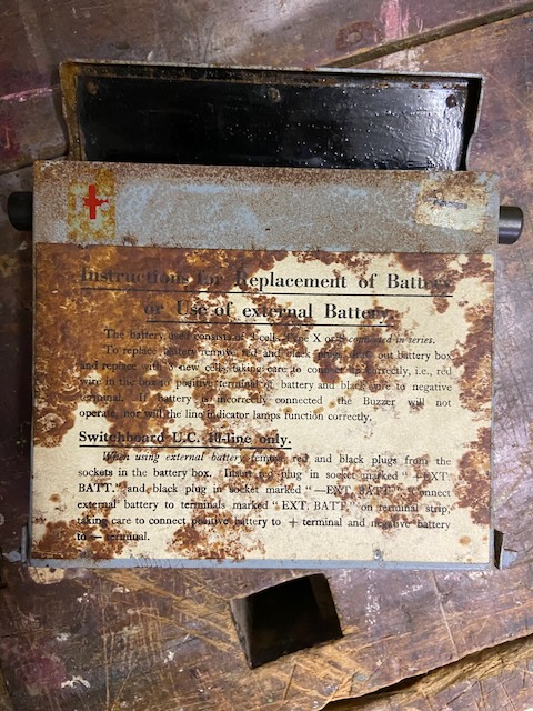
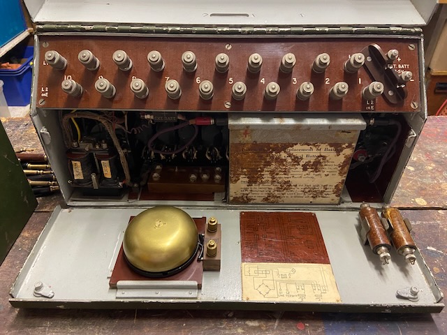
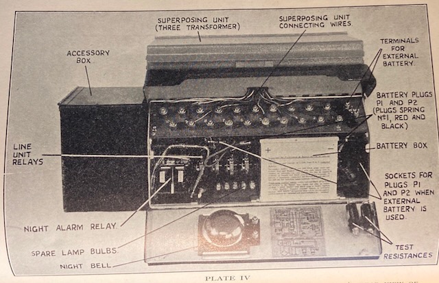
Instructions for Replacement of Battery or use of external Battery.
Switchboard U.C. 10-line only.
Typical switch boards from that era had mechanical call indicator flaps (typically only reacting to magneto call signalling). This switchboard uses self holding DC relays and DC lamps as call indicators. It works with buzzer or magneto signalling. The disadvantage in comparison to the "traditional" mechanical flaps is that it needs a battery for incoming call signalling.
Disassembled.
Disassembled.
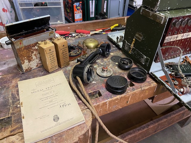
Handset, Batteries, Night alarm bell, Manual.
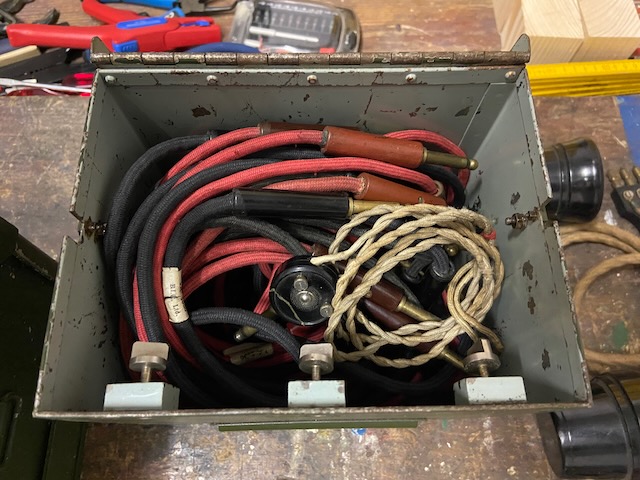
Accessories box with cords and weights.
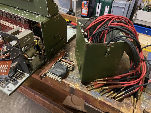
Operators unit, line unit 1, line unit 10 and common unit removed.
Disassembled, view from the back.
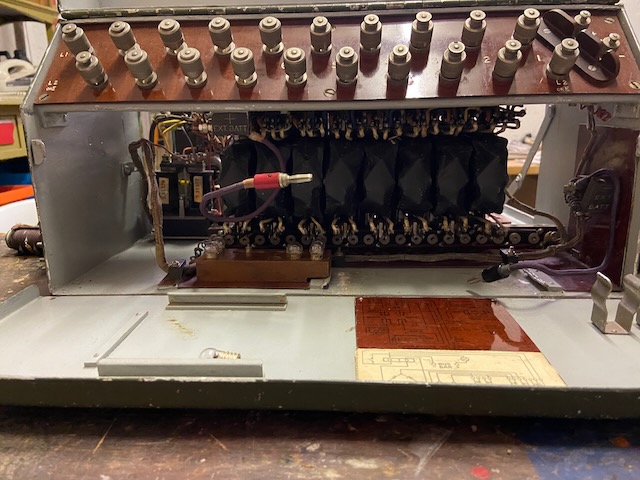
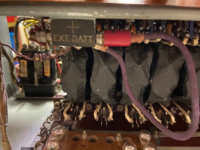
Battery +plug connected to external battery connection.
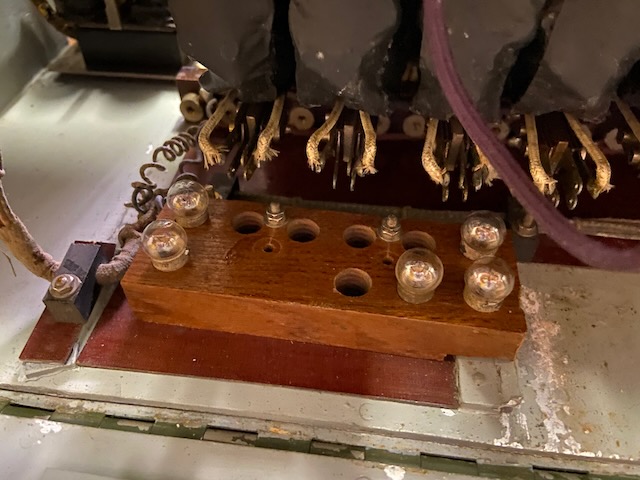
Spare lamps in the back.
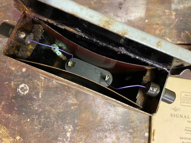
Battery box.
Battery box, 4,5V flashlight battery inserted instead of original 3x 1,5V elements.
It's a little rusty inside.
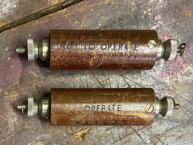
Test resistors, "Operate" = 1960 Ohms, "Not to operate" = 2960 Ohms.
Used to adjust the line relays.
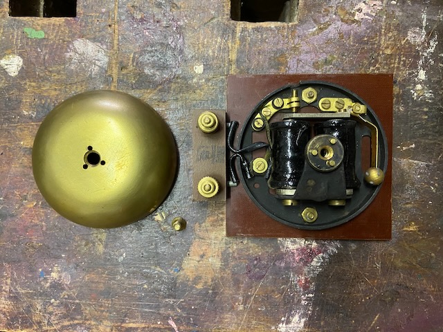
Night alarm bell disassembled.
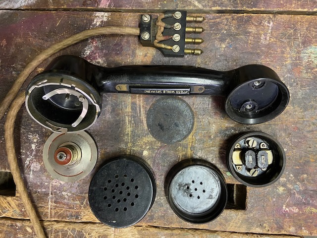
Tele Hand No. 2, disassembled.
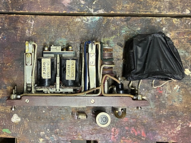
Line unit (left side) with protection paper hood taken off.
Left to right (bottom to top): B jack, relay, A jack, rectifier, lamp.
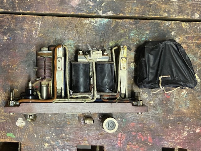
Line unit rigth side.
Left to right (top to bottom): Lamp, rectifier, A jack, relay, B jack.
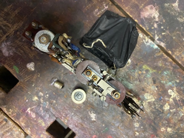
Line unit backside.
Relay adjustment screws visible.
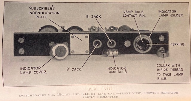
Line unit as pictured in [1].
(Differs slightly in that A and B jack are adjacent and not on top and bottom of relay.)
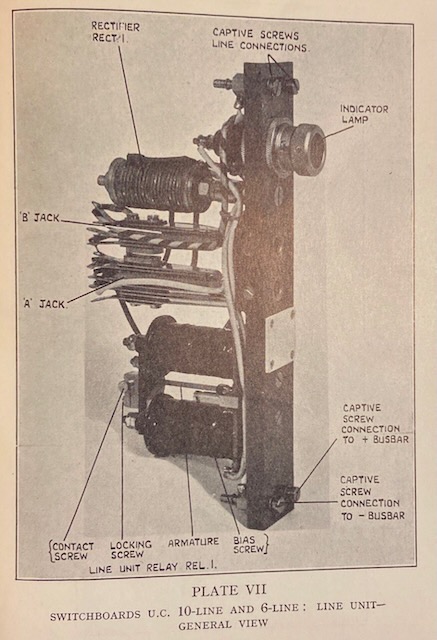
Line unit as pictured in [1].
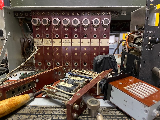
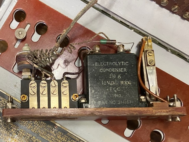
The common unit holds the magneto, buzzer, and night alarm relay circuit.
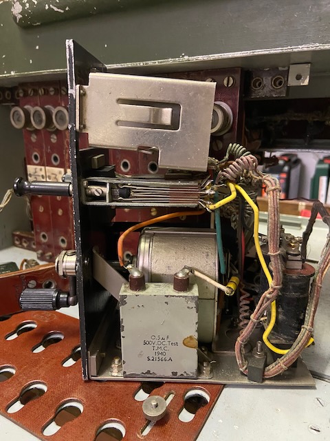
Based on the capacitor this switchboard has probably been made by T.M.C. in 1940.
(No other make indicators to be found)
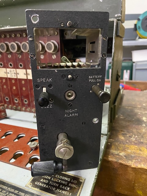
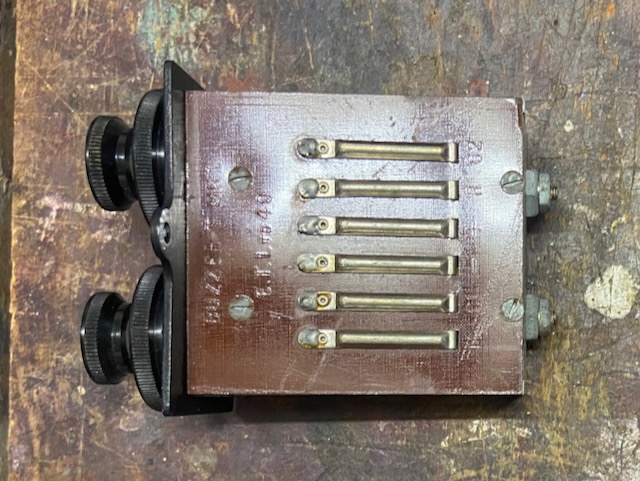
Common unit front with buzzer removed.
"Speak/Buzz" switch, night alarm socket, battery switch, magneto crank.
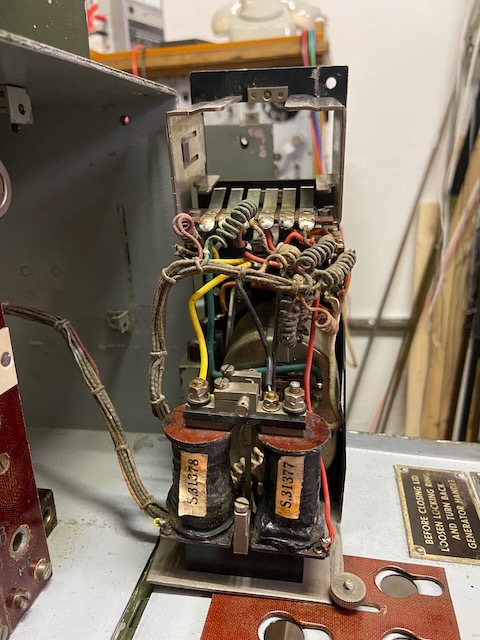
Common unit from the back.
Night alarm relay.
Buzzer T.Mk.I.
Same buzzer module as used eg. in D.Mk.V and F.Mk.I/II.
The buzzer coils serve also as anti-sidetone speech circuit.
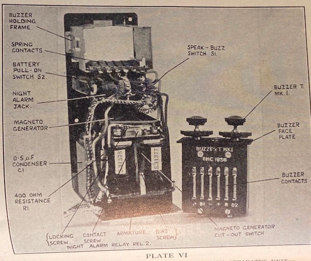
Common unit as pictured in [1].
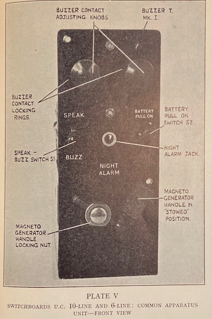
Common unit as pictured in [1].
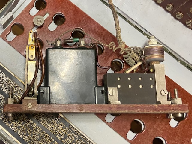
Operator's unit, left side.
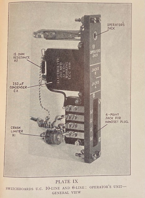
The electrolytic condenser and resistor are part of the TX circuit.
The rectifier setup is used as crash limiter in the RX circuit.
Operator's unit, right side.
Operator's unit as pictured in [1].
Ready to pack.
Night alarm bell stored, battery connected.
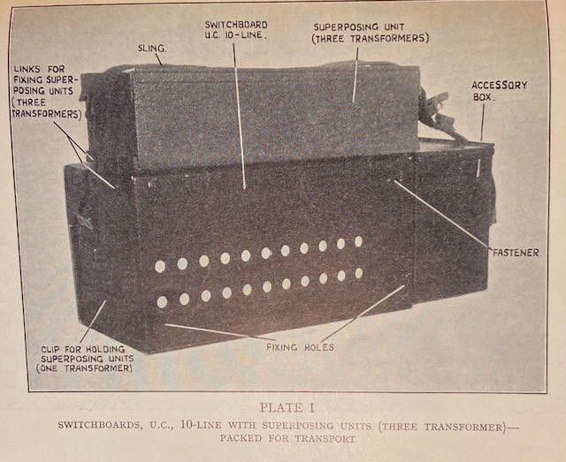
From the back as pictured in [1].
All cords stored int accessory box.
Ready for transport.
![]()
Packed as pictured in [1].
Ready to use.
Cords mounted, handset and night alarm bell connected.
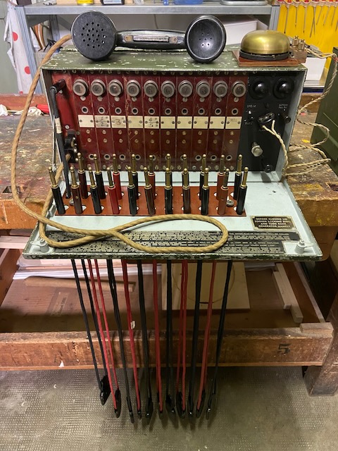
Ready to use as pictured in [1].
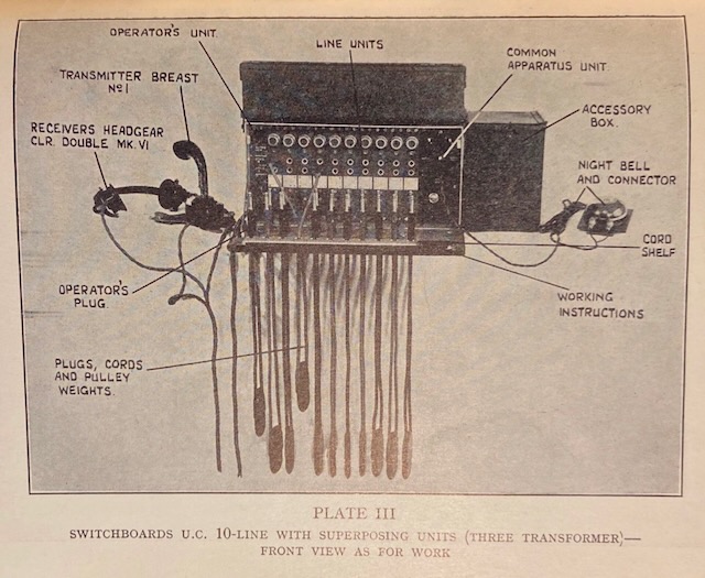
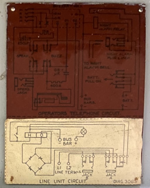
Diagram inside backside lid.
The line unit diagram is a slightly updated version (compare with below diagram from the guide).
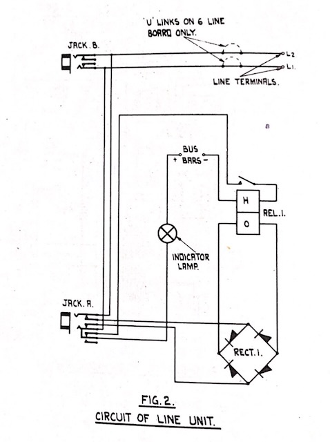
Line unit diagram from [1].
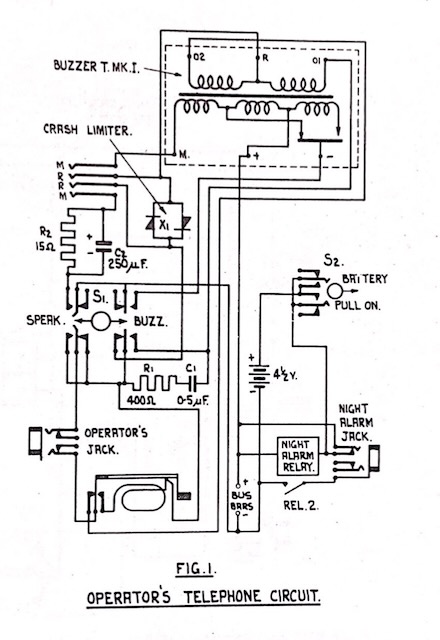
Operator's circuit diagram from [1].
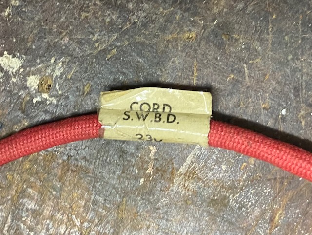
Switchboard cord label.
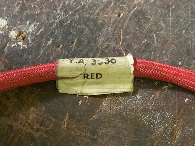
Red cord YA 3536.
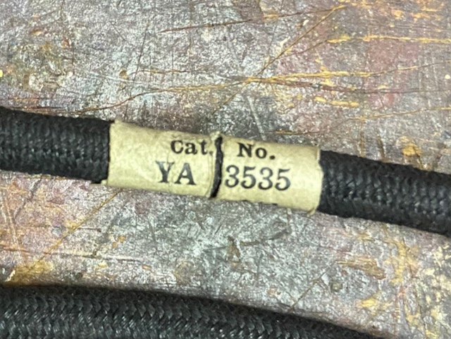
Black cord YA 3535.
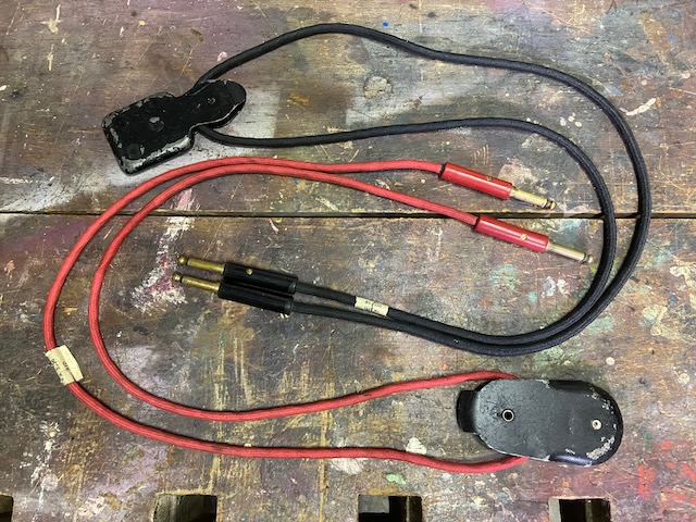
Cords with weights.
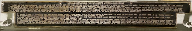
User guide inside front lid.
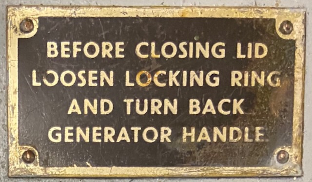
Reminder label to prevent breaking magento crank handle when closing lid.
Creative Commons Attribution-ShareAlike 4.0 International License