Find more details on U.S. field telephone history on the U.S. Signal Corps Field Telephones Timeline.
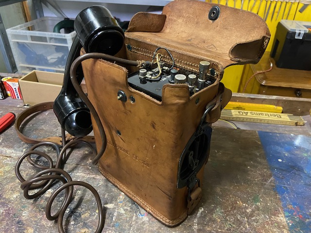
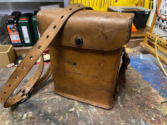
The US EE-108 is a sound-powered field telephone developed in the late 1930s and used extensively during WWII and beyond. Its core design is based on the local battery EE-8 model, with interchangeable components such as the leather case, generator, ringer, and capacitor. The EE-108 can function in point-to-point setups with other sound-powered or local battery phones and is also compatible with local battery switchboards.
Two nearly identical models, the TP-3-T1 and TP-3, were developed around the same period. These models added an optical ringing indicator, with a screw switch that enables users to select between the built-in ringer and a small neon light for signaling.
Like the EE-8 and other equipment, the EE-108 was distributed under the lend-leaese program during WWII, with over 70,000 units sent to the USSR. This particular EE-108 carries Signal Corps stamps and includes a transmitter element dated to the 1950s, indicating it remained in use with the US Signal Corps at least into the late 1950s. The Connecticut Telephone and Electrical Company manufactured this (and possibly all) EE-108 units.
The instrument is sound powered, the transmitter does not need battery power. Instead of a carbon transmitter as in local battery field instruments this instrument uses an electromagnetic transmitter (and receiver), when talking the electrical power induced in the transmitter is sent to the line. The transmitter and receiver elements are interchangeable.
Ready for use

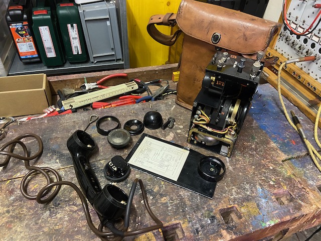
Disassembled
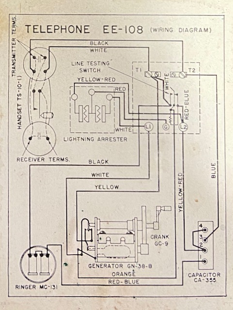
Wiring Diagram.
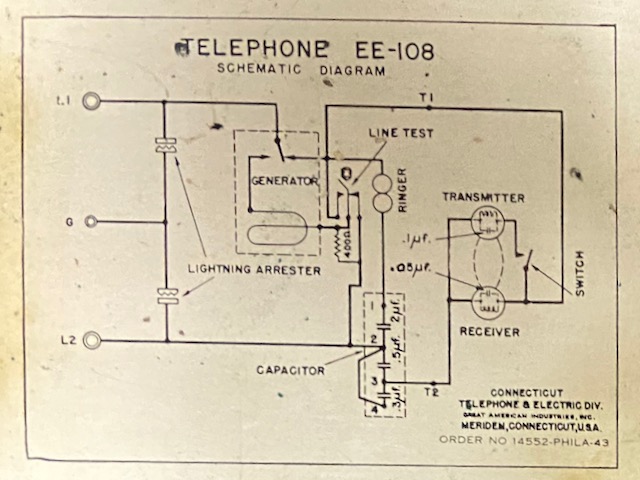
Schematic Diagram.
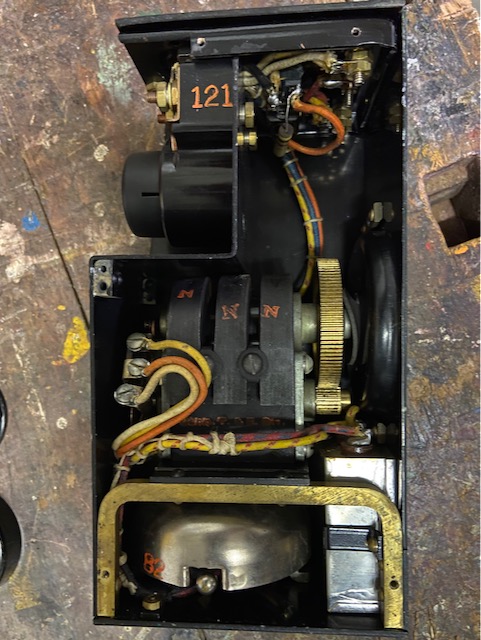
Body opened. Top left lightning arrestor. Ringer and capacitor below generator.
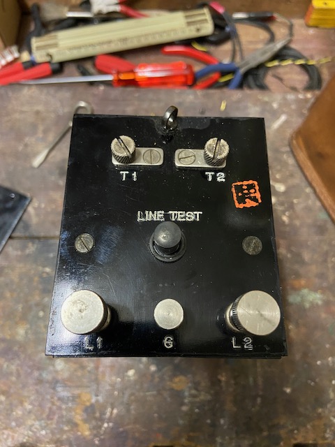
Body top. Handset connectors, T1, T2. Line connectors, L1, L2 and ground G. Line test button (If pressed and generator cranked ringer should sound when connected to working line with terminating instrument). Red signal corps inspection stamp.
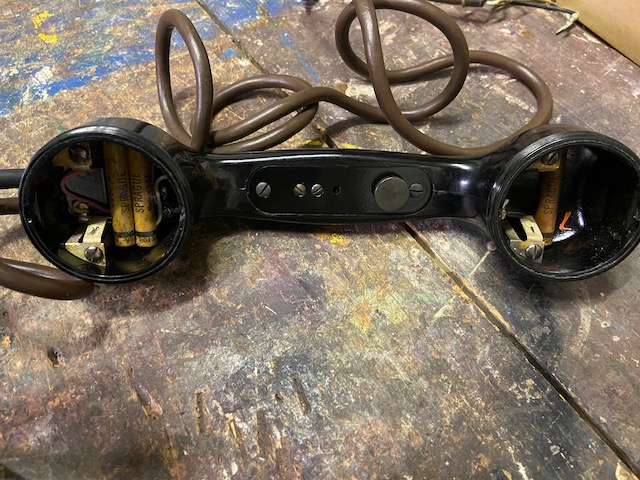
Handset type TS-10-() with P.T.T. button. Elements removed. The paper capacitors mounted in the handset (0,05uF each, 2x at TX and 1x at RX side) improve the frequency response of the circuit.
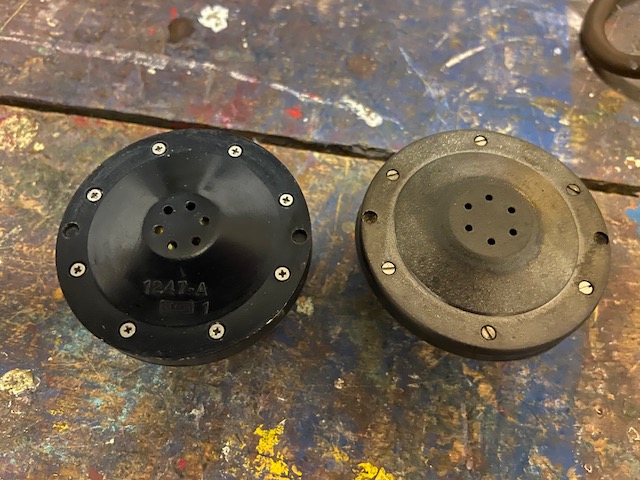
RX and TX elements back. The RX element is from 43, the TX element from 56. According to the manual they should be interchangeable.
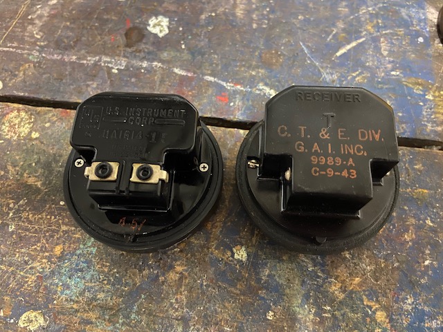
RX and TX elements front.
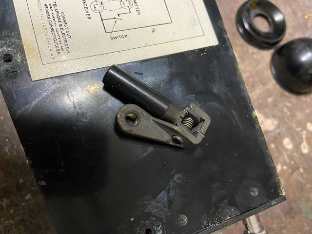
Crank handle unmounted.
Body mounted in cover. Handset cord connected and secured.
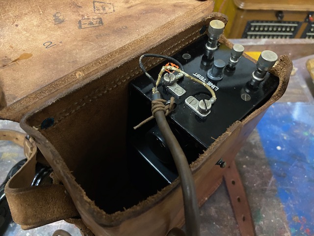
Handset stored. SC acceptance stamps inside cover lid.
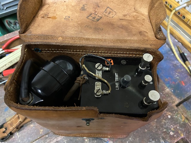
Ready for transport or storage.
Creative Commons Attribution-ShareAlike 4.0 International License