Find more details on German field telephone history on the German Field Telephones Timeline.
The first German Telegraphentruppe "integrated" (magneto and buzzer in same instrument) field telephone the "Feldfernsprecher" was introduced in 1904 [4]. After the introduction of the successor "Eiserner Feldfernsprecher" ("Iron field telephone") in 1913 [5] this instrument was also called "Feldfernsprecher bisheriger Art" ("field telephone of previous type") [1] and "Feldfernsprecher alter Art" ("... of old type") [2].
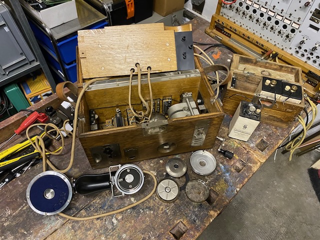
A main wood box holds the handset, a magneto, ringer, capacitor and the buzzer, the batteries are connected through an additional external wooden battery box. The buzzer coils are used as speech coils. The instrument was designed to use on single wire with earth return installations.
Device description from "V.P.K. Das Feldfernsprechgerät." [1].
The field telephone contains the following parts in a case made of oak wood, which is 34 cm long, 15.5 cm wide and 19.5 cm high: an inductor, a ringer, a buzzer that also serves as a speaking coil (induction coil), a handset that carries the receiver at the top and the microphone at the bottom, a capacitor, a switch, a switching cord and plugs, a lightning arrester and the necessary clamps, leads and buttons. In addition, a spare microphone, a spare lightning arresters and three spare screws for inside lid are housed in the box. On the lid is an ivory plaque and an alphabet board. Almost all metal parts attached to and in the box of the field telephone are made of brass and are nickel-plated, all iron and steel parts are copper-plated and nickel-plated with the exception of the receiver diaphragm and the receiver magnets together with pole shoes. The box stands on four feet attached to the bottom.
Maintenance description from "V.P.K. Das Feldfernsprechgerät." [1].
The troops are allowed to fix the following problems: Replacing the lightning rod. Cleaning of all latches and sockets that are accessible after removing the intermediate floor. Jammed inductor crank. Mark: The crank rubs against the edge of the mounting hole, the shaft does not return to the rest position after turning the crank. Elimination: The screws holding the Inductor on the floor are to be loosened and tightened again so that the screwed-in crank in the mounting hole moves freely. If necessary, loosen the screws completely and screw the inductor back in after placing a piece of cardboard underneath. Denting of the diaphragm of the receiver. Mark: Sticking of the diaphragm to the magnet at the lowest position of the magnet or inability to get the magnet close enough to the diaphragm at its highest position. Elimination: Replacing the diaphragm. Damage to the microphone. Characteristics: no or poor communication, absence of clicking after pressing the talk button or whooshing noises while holding down the talk button. Elimination: Changing the microphone. All other errors may only be eliminated by a mechanic.
The capacitor is switchable into 4 positions and allows to use the instrument as follows:
Disassembled.
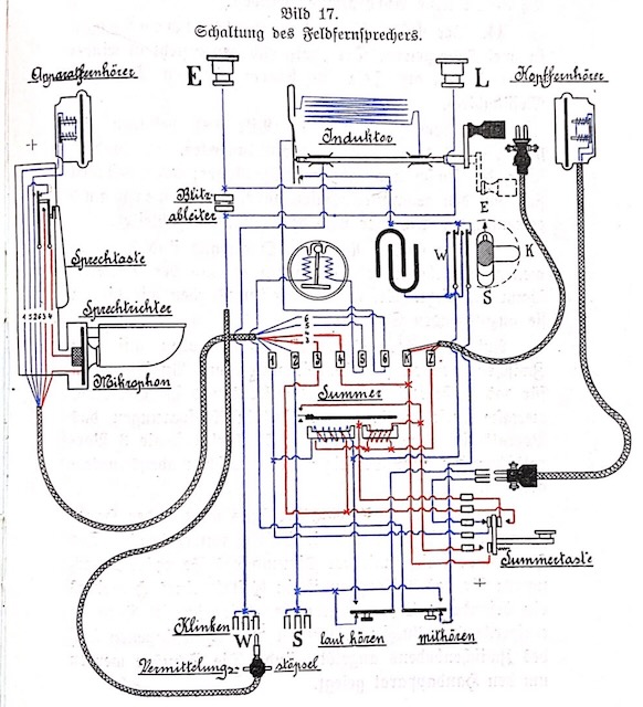
There is no diagram added to the instrument.
This is the wiring diagram from [1].
Handset with open TX side and spare microphone capsule.
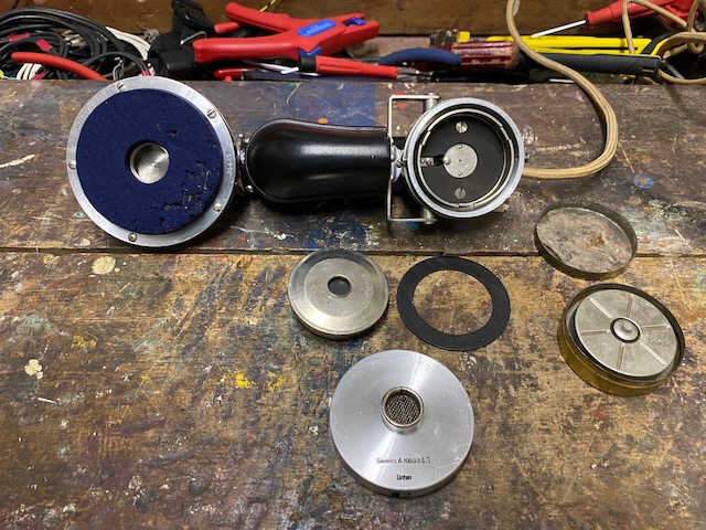
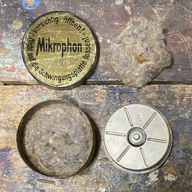
Spare microphone capsule.
"Mikrophon. Vorsichtig öffnen! Nicht auf die Schwingungsplatte fassen."
("Microphone. Open with care! Don't touch the diaphragm.")
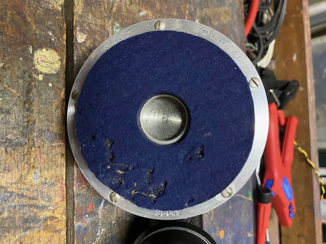
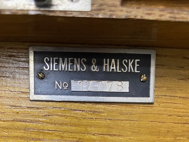
"Siemens & Halske" label on the RX side.
From ~1905 onwards the Siemens & Halske telecom production sites were called "Wernerwerk" (after Werner von Siemens) [8].
"35649", assumed to be a serial no.
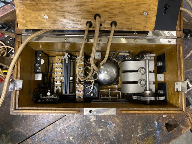
Open box.
All components mounted to the inside.
Wiring along "floor" and "walls".
In the left part the buzzer, right of it capacitor, bell, magneto.
On top between bell and magneto the lightning arrestor (between line and earth).
Bottom between capacitor and magneto the capacitor switch contraption.
To the left of the magneto the line and earth connectors inside.
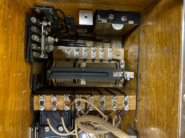
Left: Buzzer switch contraption.
Top left: receive loudness and listen in switches.
To the right of it a spare lightning arrester.
Top right: patch sockets back with some metallic cover.
In the middle the buzzer.
Below the buzzer the battery and handset connection board with color coded connectors (2 leftmost are the battery).
Neatly arranged to assemble.
Ready to use in buzzer mode.
Ready to use in magneto mode.
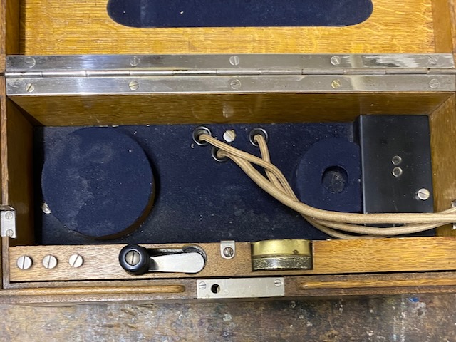
Inside cover mounted.
The inside cover sideboard houses 3 spare screws, the magneto crank handle and the spare microphone.
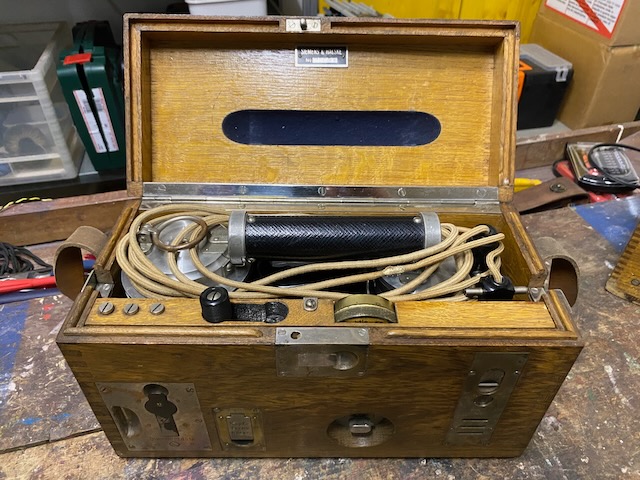
Handset and cables packed.
The inside cover provides plug holes to store the line and battery plug.
Siemens & Halske, assumed serial no.
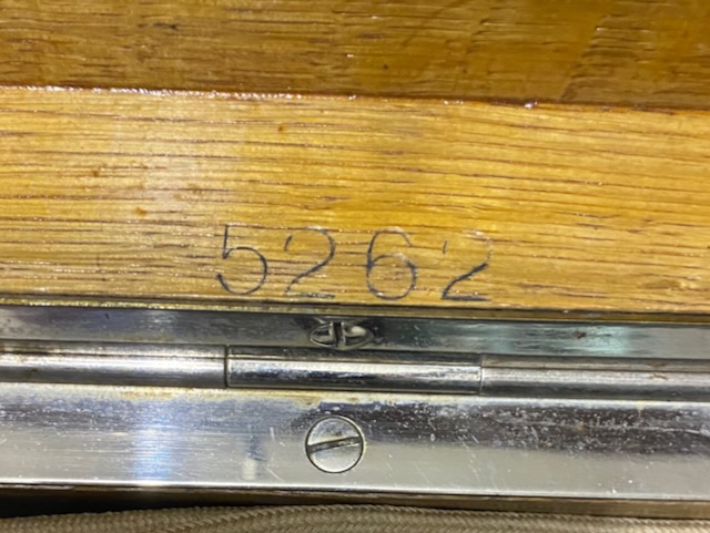
On the lid inside probably the box serial no. to match lid and box.
Number nowhere visible on bottom box part, maybe below hinge.
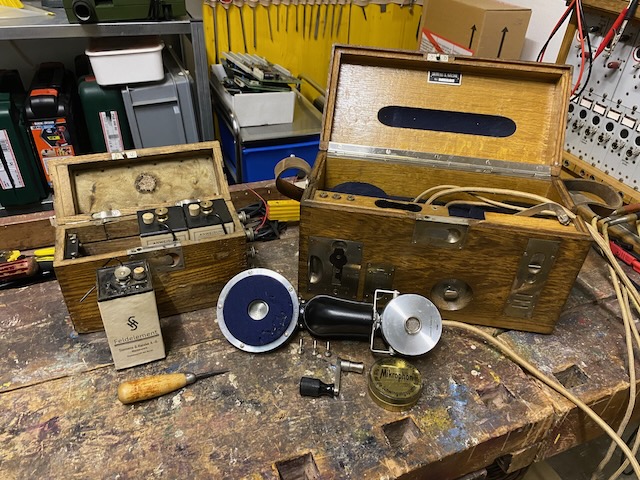
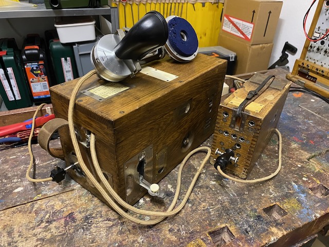
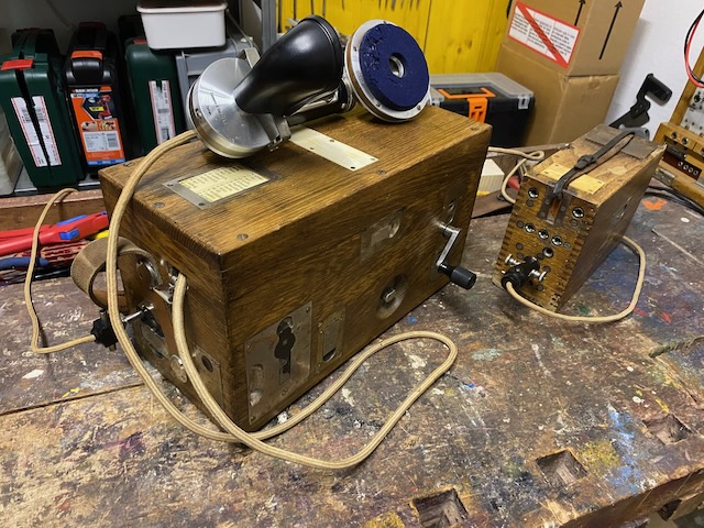
Ready for transport with battery box.
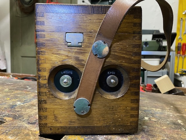
The instrument leather strap is not original.
The battery box leather strap might be original.
![]()
Front.
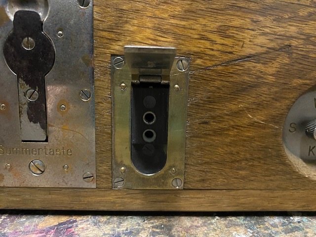
Buzzer lever, headset jack, capacitor switch, magneto lever hole with spring loaded slide-able lid.
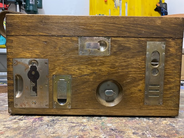
Headset jack covered by hinged lid.
Left side.
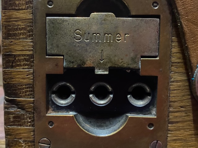
"Switchboard" sockets (here in "Wecker"= ringer/magneto position).
Receive loudness and listen in buttons.
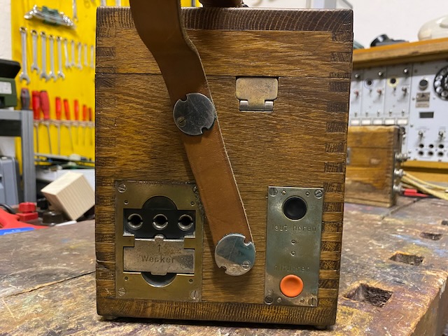
"Switchboard" sockets in "Summer"=buzzer position.
Right side with "Leitung"=line and "Erde"=earth binding posts.
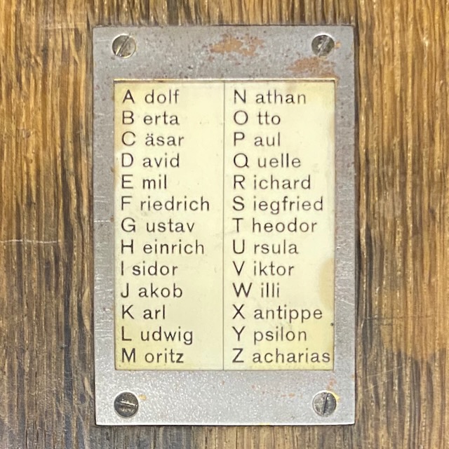
Top side.
Spelling table and an ivory label for markings.
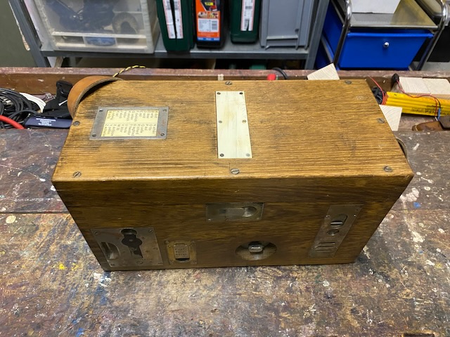
The spelling table.
(Also very well preserved or likely not original)
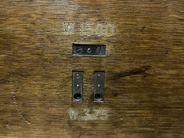
Back.
Pads which allow to switch the ringer resistance.
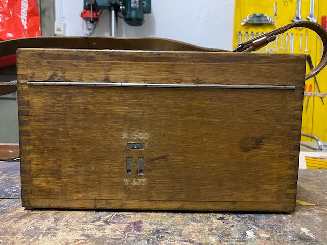
Default ringer setup is in series 2x 750 Ohm = 1500 Ohm.
Optionally by moving the two screws the ringer setup can be changed to parallel for 2x 750 Ohm = 375 Ohm.
This was used on lines with end of call DC supervision ("Selbsttätiges Schlusszeichen") [1].
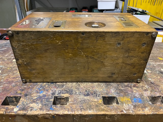
Bottom.
Metall feet in the corners
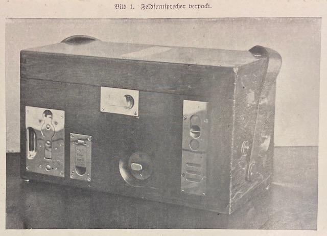
"Feldfernsprecher verpackt" (Field phone stored) from [1].
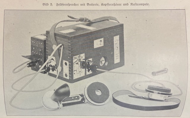
"Feldfernsprecher mit Batterie, Kopffernhörer und Ruftrompete" (Field phone with battery, headset and signalling whistle) from [1].
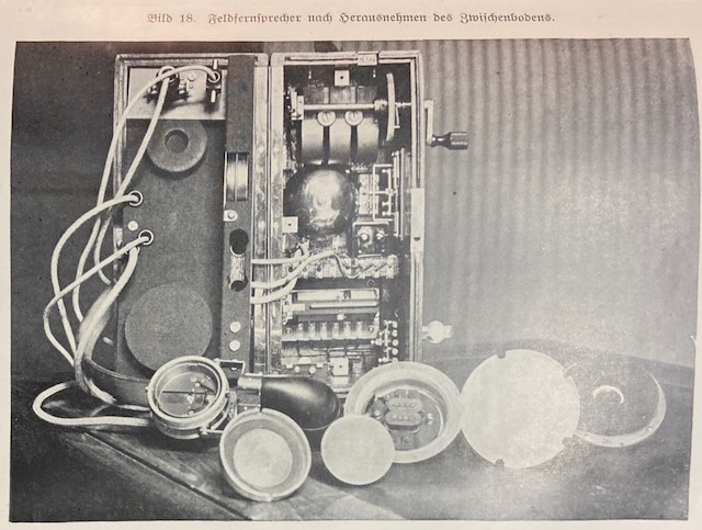
"Feldfernsprecher nach herausnehmen des Zwischenbodens" (Field phone after removing the inside lid) from [1].
Creative Commons Attribution-ShareAlike 4.0 International License