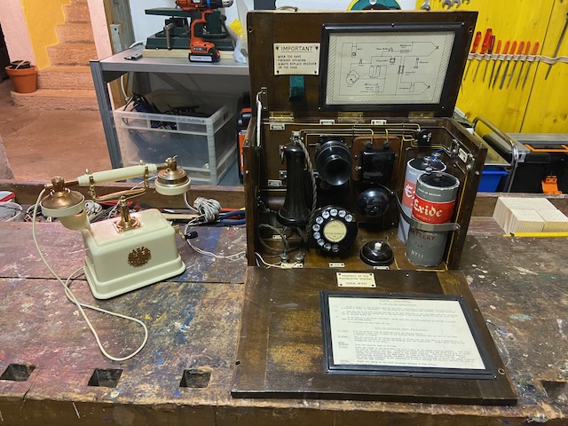
"Something completely different". It is portable, battery powered and in a wooden case, so checks quite a lot of boxes to be a kind of field telephone, though it cannot be used on an LB or also not a CB/Aut. line.
It is an instrument used in British schools in the 1930ies for demonstration of the newly introduced automatic telephone technology [2].
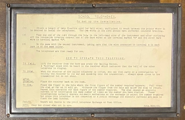
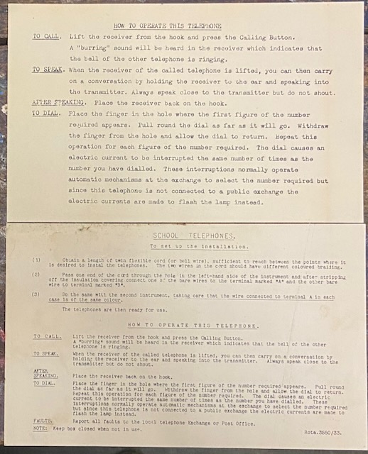
Transcript from the user guide inside the front lid:
SCHOOL TELEPHONES.
To set up the Installation.
(1) Obtain a length of twin flexible cord (or bell wire), sufficient to reach between the points where it is desired to instal the telephones. The two wires in the cord should have different coloured braiding.
(2) Pass one end of the cord through the hole In the left-hand side of the instrument and after stripping off the insulation covering connect one of the bare wires to the terminal marked "A" and the other bare wire to terminal marked "B".
(3) Do the same with the second Instrument, taking care that the wire connected to terminal A in each case is of the same colour.
The telephones are then ready for use.
HOW TO OPERATE THIS TELEPHONE.
TO CALL. Lift the receiver from the hook and press the Calling Button. A "burring" sound will be heard in the receiver which indicates that the bell of the other telephone is ringing.
TO SPEAK. When the receiver of the called telephone is lifted, you can then carry on a conversation by holding the receiver to the ear and speaking into the transmitter. Always speak close to the transmitter but do not shout.
AFTER SPEAKING. Place the receiver back on the hook.
TO DIAL. Place the finger in the hole where the first figure of the number required appears. Pull round the dial as far as it will go. Withdraw the finger from the hole and allow the dial to return. Repeat this operation for each figure of the number required. The dial causes an electric current to be interrupted the same number of times as the number you have dialled. These interruptions normally operate automatic mechanisms at the exchange to select the number required but since this telephone is not connected to a public exchange the electric currents are made to flash the lamp instead.
FAULTS. Report all faults to the local telephone Exchange or Post Office.
NOTE: Keep box closed when not in use.
Rota.3550/33.
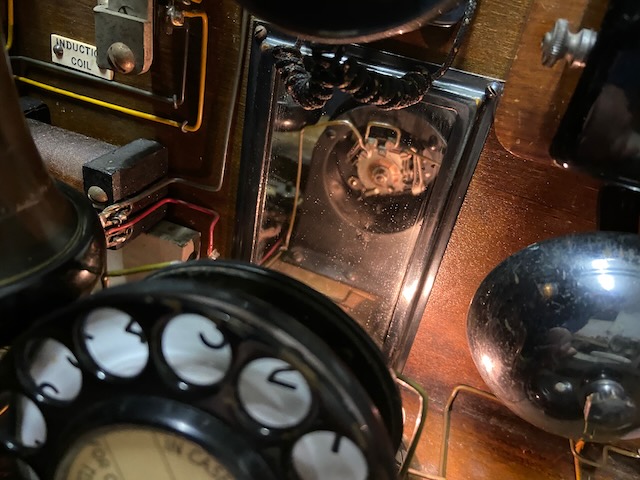
A mirror behind the dial allows to see the dial mechanism.
Ready for service.
Connected to a toy DC house telephone which operates with the same principle (On this one cranking the "magneto" activates a switch which feeds the remmote ringer).
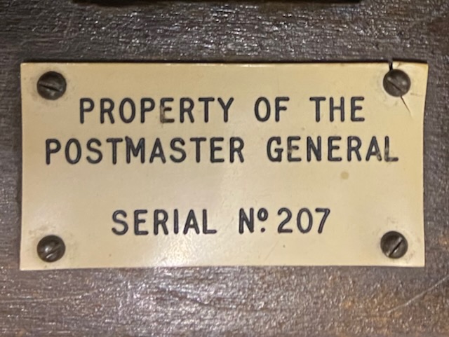
Property of GPO not the schools.
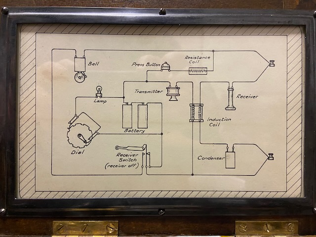
The DC ringer is fed by the remote device battery (when local on-hook and remote off-hook and button pressed).
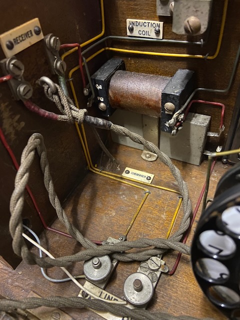
The transmitter is fed by the local battery (when off-hook) and a simple P/S induction coil transmits the voice current to the line.
The capacitor (condenser) blocks the DC ring current.
The lamp is in circuit with the dial and the batteries, when dialling the current starts to flow and is interrupted by the dial pulses, this circuit is independent of the hook switch status.
The user guide inside the front lid (see above for transcript).
Below the visible user guide another sheet with perhaps an older versions was found (with only the operate and not the setup instructions).
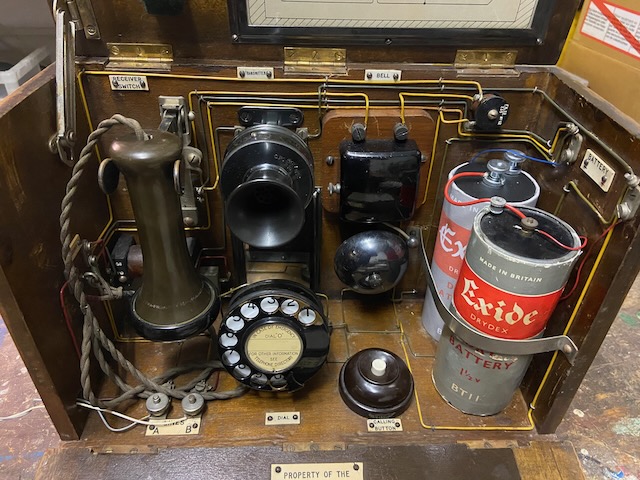
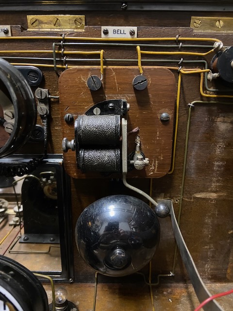
All components are mounted to the inside of the box and the wiring is visible and color coded to easy find what is connected to what and compare with the diagram.
All components are clearly labeled.
The induction coil and the condenser in the box left corner.
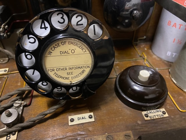
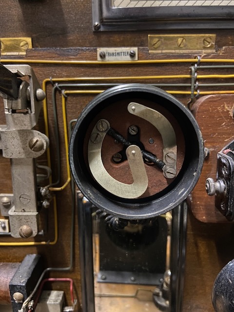
The GPO type No. 10 dial and the calling button.
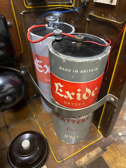
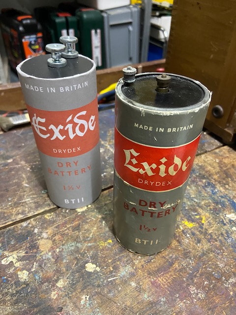
2x 1,5V BT II Cell (the front one is a not working original, the back one a simple replica).
The dial back mechanism can be observed in the mirror.
Ready for storage.
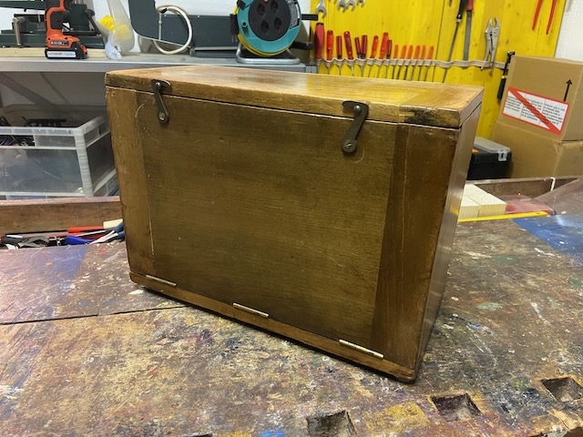
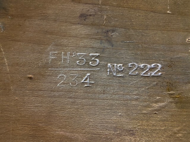
On the back the serial no.
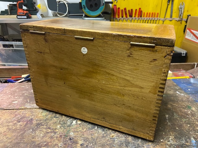
On the bottom pressed in the type designation.
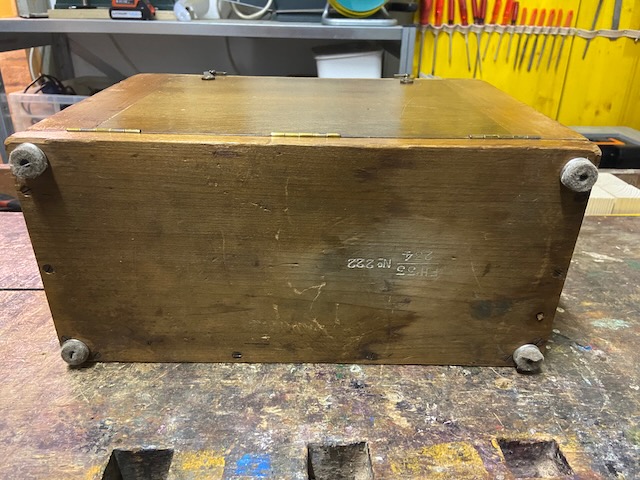
Telephone No. 222, FH designates the maker: GPO Factory, Holloway, London, 33 indicates the year of make, and 234 designates revision (Mark) 1.
The cap removed from the DC ringer.
The belly type receiver.
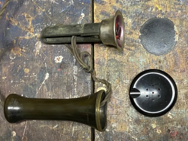
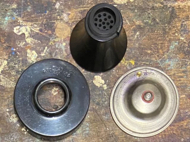
The transmitter No.2 case.
Transmitter No.2 capsule, lid and mouth piece.
The batteries.
I assume the original and the replica are clearly distinguishable.
The replica contains two 1,5V AA (IEC R6) Cells.
Creative Commons Attribution-ShareAlike 4.0 International License