The Feldfernsprecher 26 was the "in between wars" german field telephone. Developed in 1926 as successor to the Feldfernsprecher 17 using the same basic construction (with similar size and weight) but adding a hook switch and capacitors to make it CB lines compatible. It is also compatible to the buzzer module for the FF 17. The FF 26 was developed and manufactured by C. Lorenz AG and by a couple of subcontractors [8].
The here presented sample was made in 1935, the last production year [6]. The magneto is made by Siemens & Halske, the capacitors are by Hydra and the coil and ringer are made by C. Lorenz AG. This model has a bakelite only buzzer/line connector block, earlier models had a metallic cover on the block (see examples in the gallery below). There is no marking indicating which company did the assembly, perhaps C. Lorenz.
FF 26 description from "Fernsprechgerätelehre, B1" [3] (Translated from German):
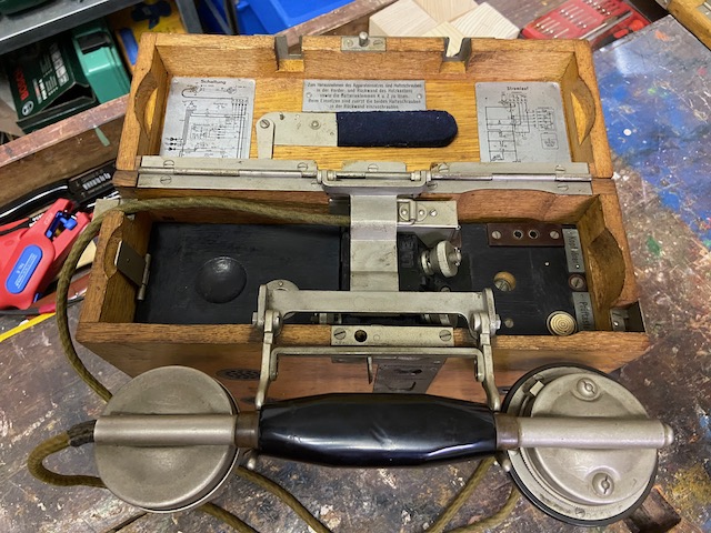
Telephone instrument with microphone battery (2 elements in series) installed in a wooden box with hinged lid. Plug-in handset with receiver, microphone and loudness button to be placed on the folded out hookswitch cradle. Two jacks for switching purposes. Device for connection to post office lines for operating mode SB, ZB. Sockets for connecting a headset and a buzzer, test button for testing the inductor and ringer. Entire circuit arrangement combined in a removable insert.
(Original: "In aufklappbarem Holzkasten eingebauter Fernsprechapparat mit Mikrofonbatterie (2 Feldelemente hintereinander). Einsteckbarer Handapparat mit Fernhörer, Mikrofon und Lauthörknopf zum Auflegen auf herausgeklapptem Gabelträger. Zwei Klinken für Vermittlungszwecke. Einrichtung für Anschluss an Postleitungen für Betriebsart SB, ZB. Buchsen für Anstecken eines zweiten Fernhörers und eines Summers, Prüfknopf zum Prüfen des Induktors und Weckers. Gesamte Schaltanordnung im herausnehmbaren Weckereinsatz vereinigt.")
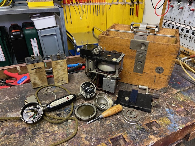
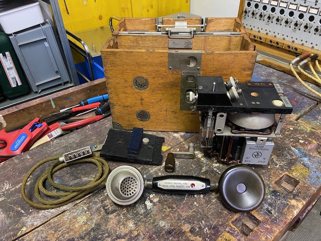
Disassembled.
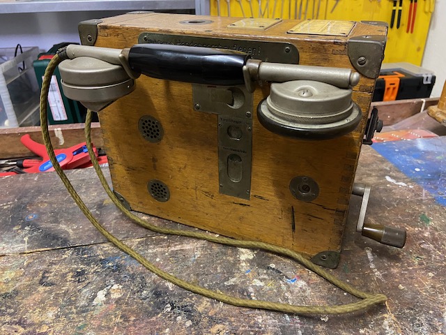
Ready to use.
The instrument is used with folded out hook cradle and closed top lid.
The hook switch is used in LB and CB mode.
The button in the lid center can be used to activate the optional buzzer unit though the lid.
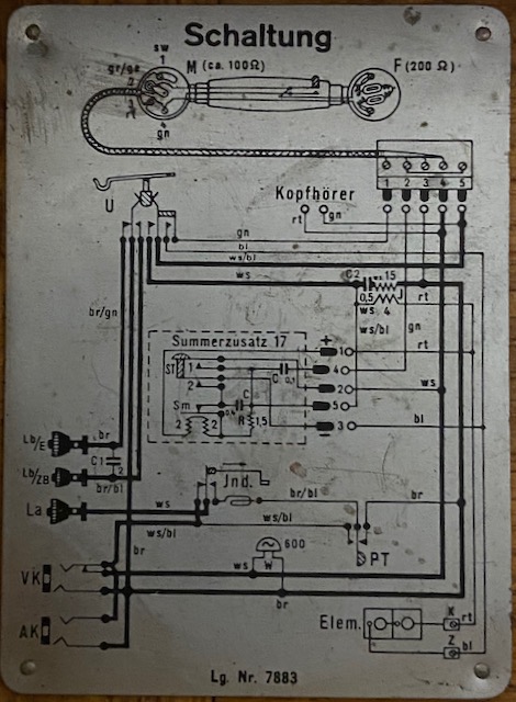
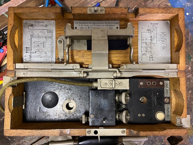
Wiring diagram.
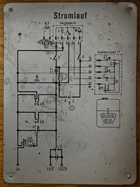
Electrical diagram.
Spelling alphabet and label for markings.

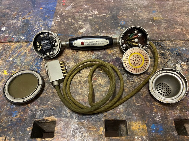
The handset is based on the postal/civil ZB/SA 24 but adding the red "Push to hear louder" button.
The RX side is fix, the TX side is capsule based, it takes a Lorenz type capsule.
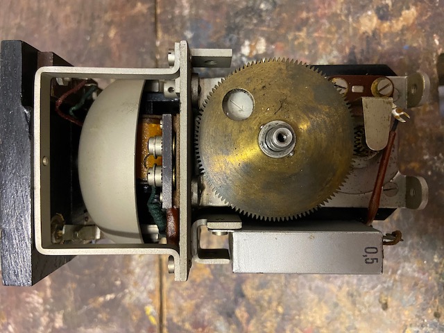
The body module has mounted all the parts.
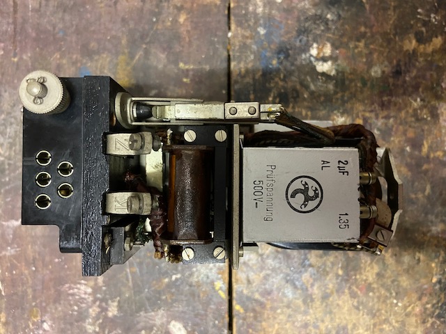
This is the front side when mounted.
Front left the hookswitch assembly and beneath that the line patch sockets.
The 0,5uF Hydra capacitor does block ringing current from the RX circuit.
Here on the left (top) the sockets for the buzzer module (Summerzusatz 17).
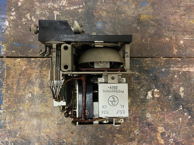
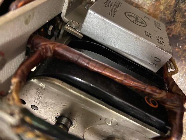
This is the side pointing left towards the battery compartment when mounted.
Below the battery connectors (K = "Kohle" = carbon = +, Z = "Zink" = zinc = -).
Below that the coil and further below the 2uF capacitor which is active when used on CB lines to block the CB DC current when on hook.
The Hydra made capacitor's mfg. date points to a device mfg. date of 1935.
Back side when mounted.
The clapper ball of the ringer is visible in the bell's opening.
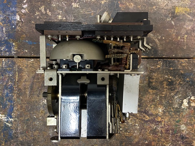
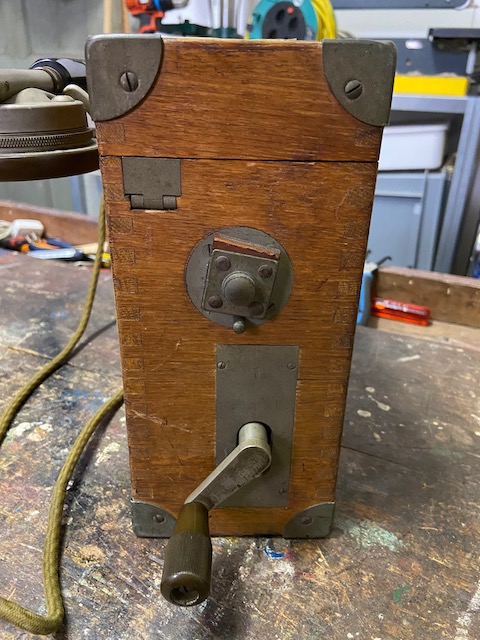
Side pointing right when mounted, where the crank handle is mounted to the magneto.
The magneto gearing is about 6:1 (generating ~18Hz ringing current when cranked with 1/s).
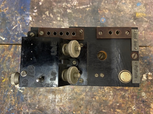
Top of body module.
For an LB connection the two binding posts on the right are used (La and Lb/E), for CB connections LA and Lb/ZB is used.
The pin between La and Lb/ZB is pushed by the hook cradle and actuates the hook switch assembly below it.
On the right the white "Prüftaste" button for line test.
Top left the 5 prong handset socket and to the right of it the 2 prong optional headset socket.
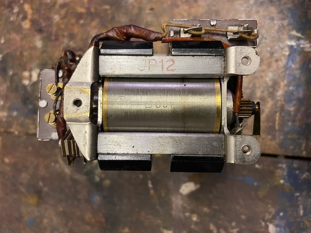
The magneto is the Siemens made type F.ind.30 (here subtype a2) also found e,g, on this Siemens made Lineman's instrument or the Swiss Modell 32.
400 Ohm magneto.
The Siemens mfg. code JP12 points to December (12) 1934 (P) as mfg. date.
Ready to assemble.
The empty box.
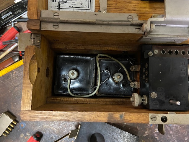
Body is mounted inside right, left is the battery compartment.
Inside the lid there is the buzzer button assembly: the now folded down lever has to be folded towards the right center and then reaches over the button pin which pushes the lever pin into the buzzer when mounted.
![]()
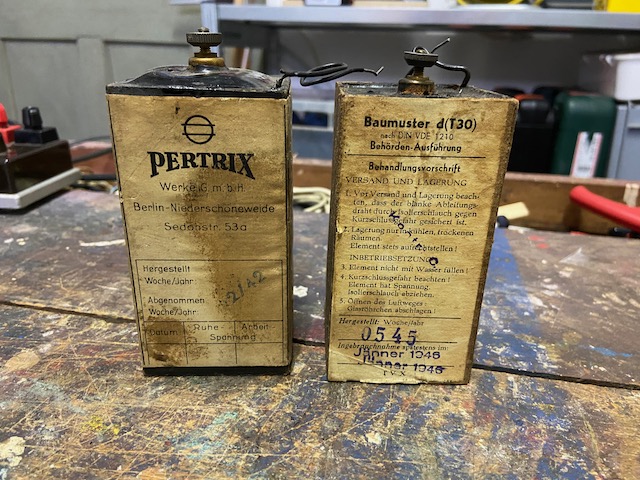
The instrument uses 2 1,5V "Feldelement" type (IES S4) dry elements.
(These are used originals made during WWII)
Elements mounted.
Body and battery lid mounted.
Hook cradle folded out with handset in place.
Crank mounted.
The crank hole is covered by a spring loaded lid when crank is out.
Hook cradle folded in, handset and crank handle stored.
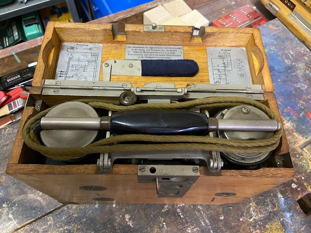
Ready for transport.
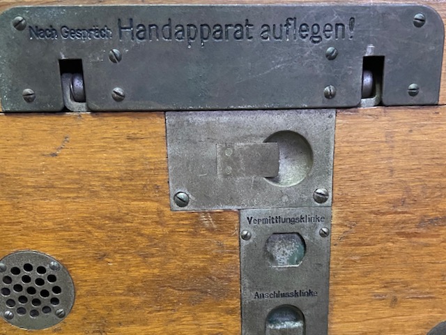
"Nach Gespräch Handapparat auflegen!": Put handset on cradle when call finished.
"Vermittlungsklinke": Switchboard socket - to connect another instrument to this instruments line.
"Anschlussklinke": to connect this instrument to another instruments line (using the "Vermittlungsklinke" on the other instrument).
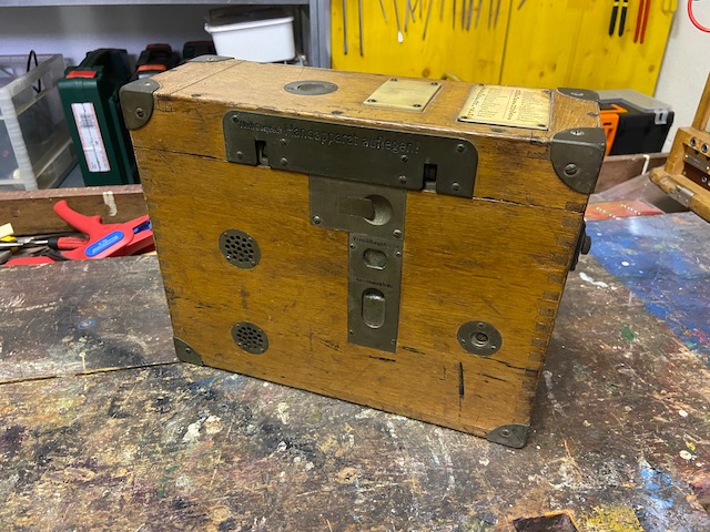
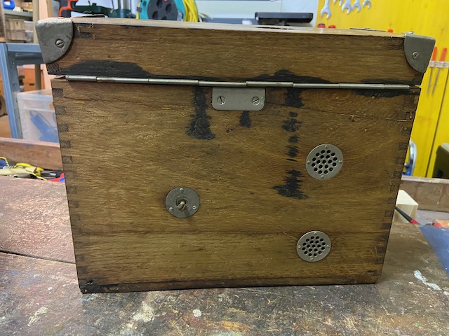
Backside.
The body module is hold by two screws on the back.
The battery compartment is ventilated from the back also.

This is the backside from a slightly older (unfortunately incomplete) instrument, ~1931 or older.
On this older instruments the body was hold by only one screw from the back (as mentioned also in [1] for older instruments).
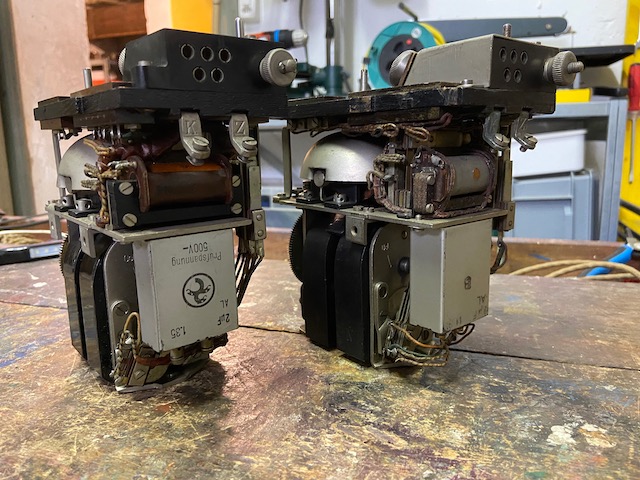
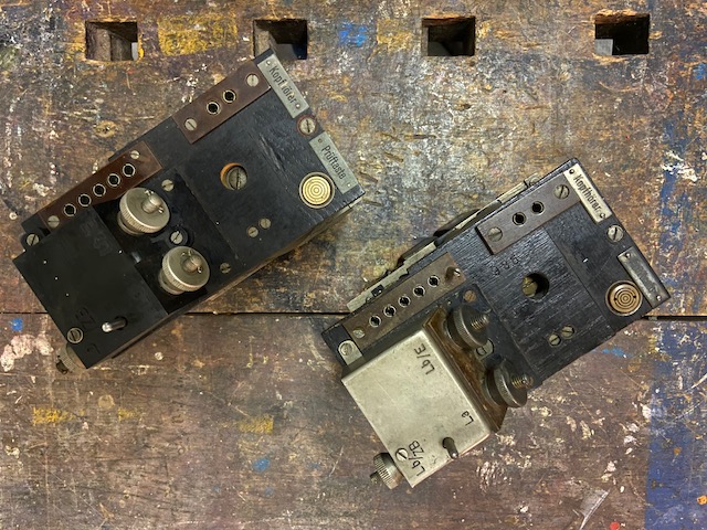
On the left the 1935 made instrument with bakelite block on top, on the right an older one, perhaps 1931 (the capacitor dates are blurred/wiped out) with a metal cover instead of the bakelite block.
Everything else apart from the connector block material is identical.
Coil and ringer are Lorenz made on both instruments.
Backside of modules.
In the back the "~1931", in front the "1935".
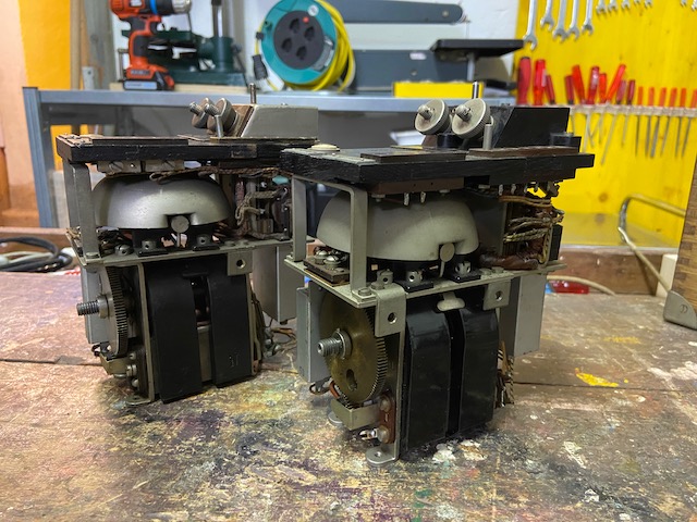
From top.
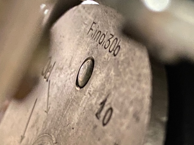
The magneto in the "~1931" instrument is also Siemens type F.ind.30 (here subtype b).
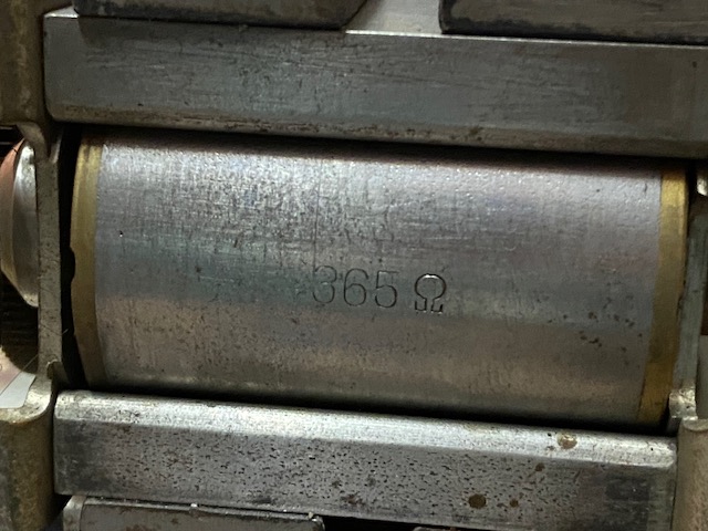
365 Ohm compared to 400 Ohm on the "1935" instrument.
Creative Commons Attribution-ShareAlike 4.0 International License