The F-27-0 was developed by Siemens Austria in 1981 according to the included diagram initial release date [1]. It was in use by the Austrian armed forces up to at least 2011 according to "Soldat 2011. Leitfaden für den Wehrdienst" [2]. The Siemens product name is SFT 800-A. The case, body and handset are made of plastic and sealed. It supports LB and CB operation and also includes a rotary dial unit for direct attachment to automatic lines. The handset is based on the Swiss FTf 50 handset (which was developed by the Swiss Siemens subsidiary), even the used RX and TX capsules are of Swiss make.
The mix of technologies used is interesting, the speech circuit is a traditional passive anti-sidetone setup using an electromagnetic receiver and a carbon transmitter. The magneto is electromechanical, and the dial unit is a based on a type N38-R rotary dial mechanism. So far a setup based on traditional proven technology. But then the receiver/generator for the local ringtone and optical ring indicator is based on an active design using transistors and even an integrated circuit. My assumption is that the MTBF of the instrument is anyway already decreased by using this electronics board (including an ESD sensitive CMOS Timer IC), then why not going the full way and implement all functions electronically like e.g. the Norwegian TP-6N, plus adding a button based dial unit? Or on the other hand if using an electromechanical setup for everything else why not adding some clapper based ringer like e.g. the TA-43/PT?
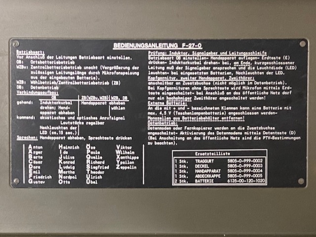
From the user guide inside the instrument top lid (Translated and slightly abridged):
Choose mode before connecting to line. OB: Local battery, WZBu: Pseudo central battery (Reach extension by using the local battery for tx supply), WZB: Auto./Central battery, DB: Data.
Connection setup outgoing: OB: Crank magneto, lift handset, WZB/WZBu/DB: Lift handset and dial, Incoming: Acoustic and optical ring signal (Adjustable volume), Talking: Lift handset and push P.T.T. lever.
Test - Magneto, ring signal, loop: Use mode OB, handset on-hook, push earth button and crank magneto. If the instrument is working and the loop is closed then the ring signal is activated.
Headset, second handset: can be connected to additional connector (not when is use for data mode connection). For sets without P.T.T. button earth button is used to activate microphone. When connecting to the public network only use high impedance headsets!
External battery: Connect to external +/- terminals. Maximum 4.5V. Take out D-Cells!
This is probably the strangest field telephone feature ever. On this instrument the magneto handle drives a belt driven gear where the belt can be changed to a different set of cogs for a "double speed", "50Hz" instead of "25Hz", ring signal generation (assuming 3/s cranking speed). To change this gearing the instrument has to be opened. The dial disc lid is marked with "25Hz" and "50Hz" and by mounting that lid with one or the other label on top the respective magneto speed mode would be indicated. I cannot come up with a reasonable explanation when this feature would be of any use? The user guide in "Soldat 2011. Leitfaden für den Wehrdienst" [2] does not mention this option.
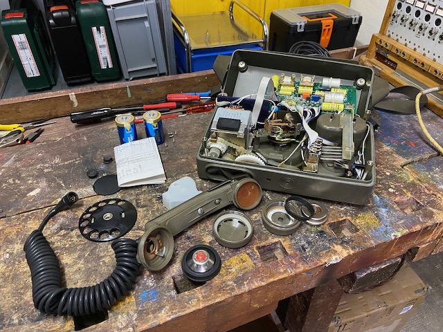
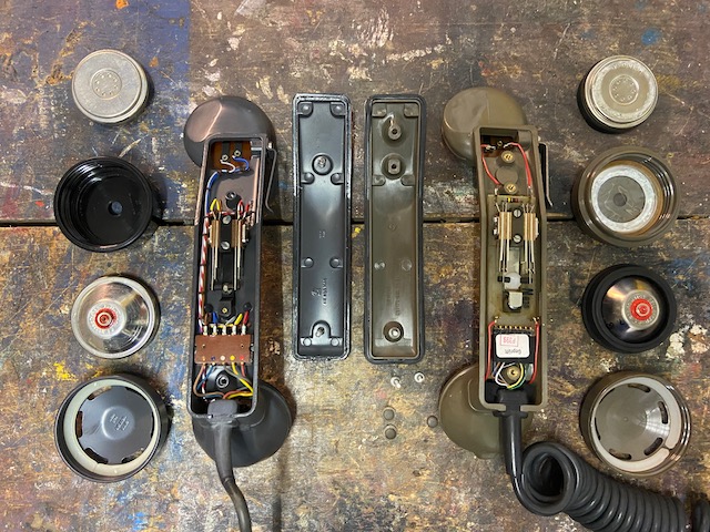
Disassembled.
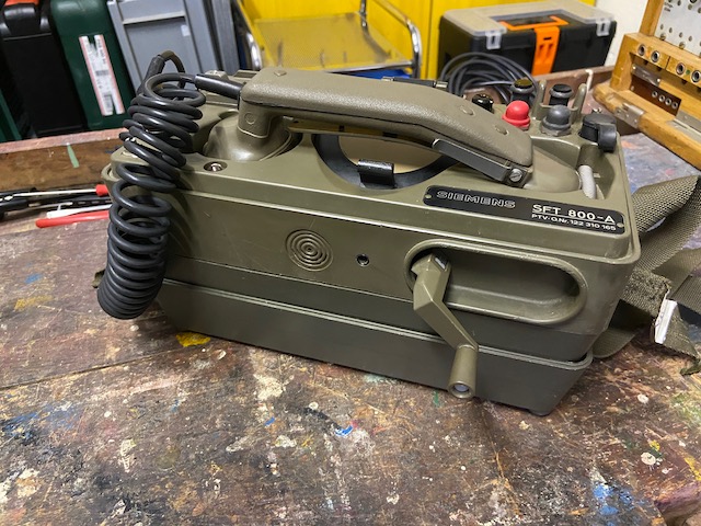
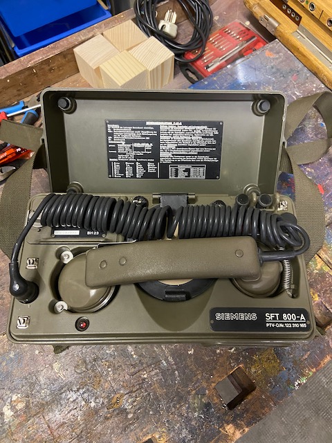
Ready to use.
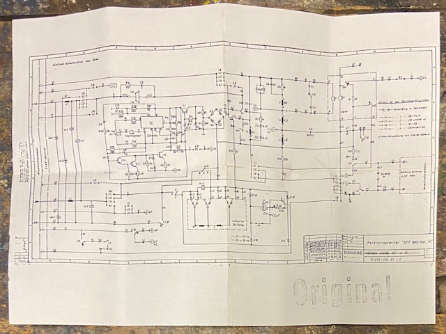
The electrical diagram is added as folded A4 paper inside the instrument body.
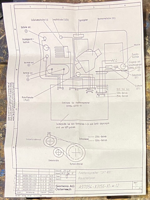
On the back of the sheet is the cabling and mechanical diagram.
Inside the top lid the user guide, spelling table and spare parts list.
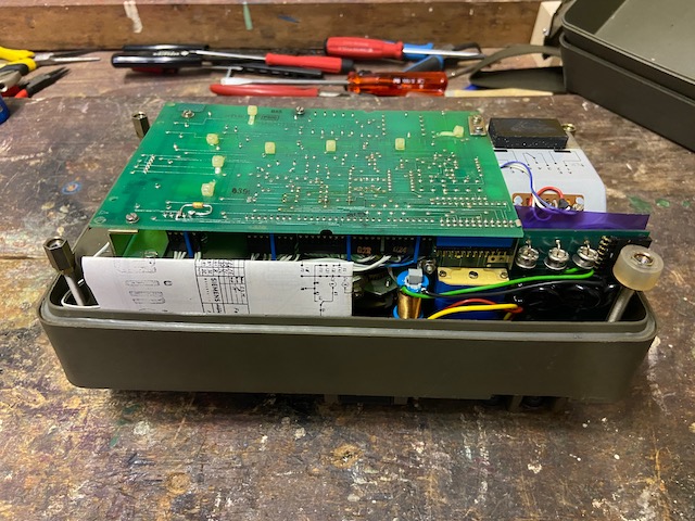
Bottom cover removed.
The diagram sheet slid in.
At the bottom the circuit board.
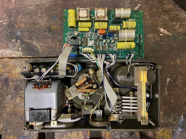
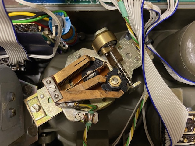
The electronics board removed and "folded" out.
In the center the back of the dial.
On the right 5 microswitches actuated by the hook switch mechanics.
On the left on top of the magneto the line board with some lightning protectors and choke coils.
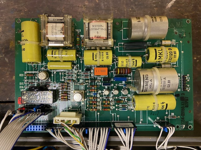
The electronics board.
More than 50% of it is dedicated to generate the ringing signal tone.
The trafo at the top center is used for the transmission circuit anti-sidetone setup.
From the identical trafo to the right only a single coil is used as choke coil.
The relay on the left is activated by the magneto current to put the magneto in the line.
The TO-99 type IC on the right of the relay is a CMOS timer IC (7555) to generate the ringer tone frequency.
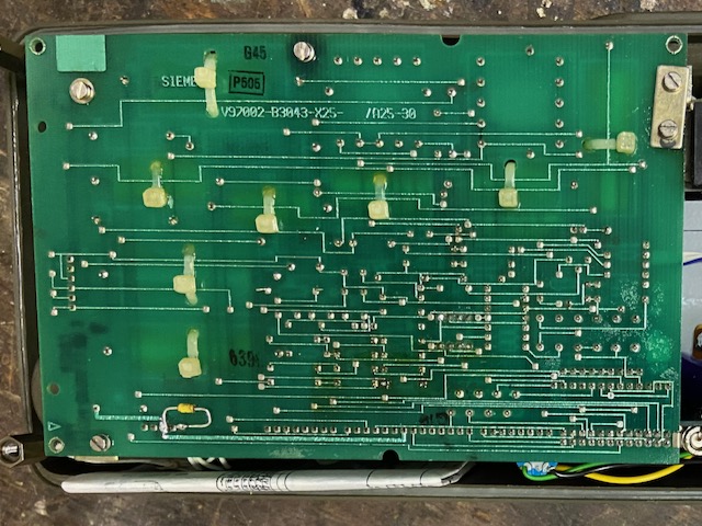
The other side of the eurocard size two layer printed circuit board.
The dial is a standard german N38-R setup.
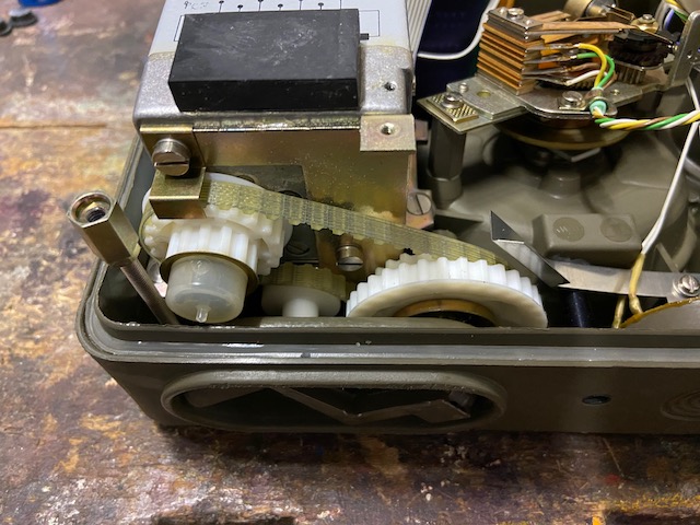
The magneto gearing.
In normal position the magneto crank drives the magneto gear 1:1 over the drive belt.
The magneto gear itself has an 1:8 ratio resulting in ~25Hz when cranking 3/s.
The drive belt can be changed to 2:1 cogs then resulting in 50Hz when cranking 3/s.
I cannot come up with a reasonable explanation when this feature would be of any use?
The empty plastic box.
![]()
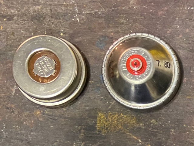
The handset based on the swiss FTf 50 handset but made entirely of plastic.
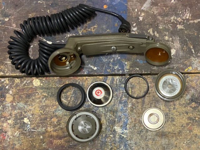
The elements are swiss made (RX Autophon, TX Zellweger).
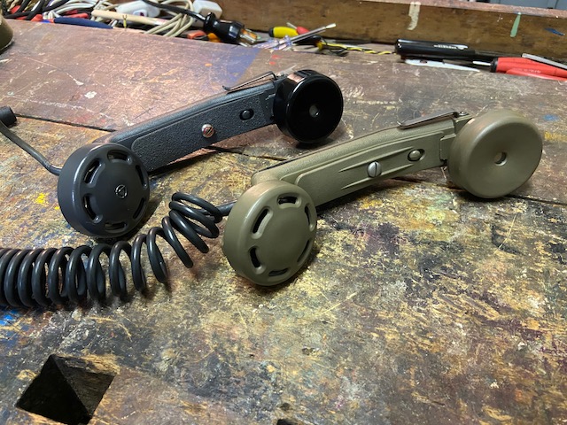
A FTf 50 and the F-27-0 handset compared (30 years in-between).
A FTf 50 and the F-27-0 handset compared (30 years in-between).
From top left: Battery compartment, ringer volume, dial, mode switch, spring loaded line binding posts, earth connection.
Below the binding posts: Red earth button, data button, connector for headset or data equipment (FAX, Modem).
On the left the handset connector and the external battery connectors.
Bottom leftish the ringing indicator light.
The dial is covered by a protective lid.
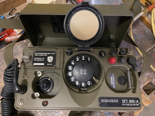
The mode switch: OB = LB, WZBu = CB with local battery TX support, WZB = CB, DB = Data.

Handset stored.
Ready for transport.
![]()
Creative Commons Attribution-ShareAlike 4.0 International License