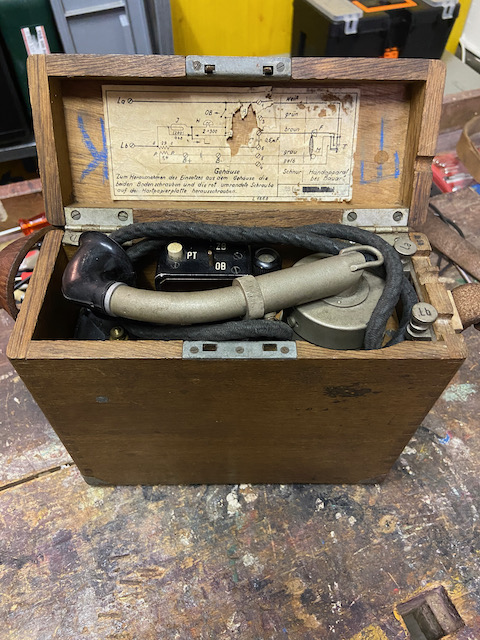
The German Streckenfernsprecher (Lineman's telephone) from ~1907 [5] and it's successor from ~1933 (assumption based on diagram in my device) are compact and lightweight (for it's time) line technicians field telephones. This instruments were used when building and troubleshooting telephone lines. The "1907" models were also used by the German army signal corps during WWI as type "M15" [4] (or according to another source "M5" [5]). One of my earlier models (capacitor date 1928) is marked R.T.V (Reichstelegraphenverwaltung) and the later model (capacitor date 1938) is marked R.P. (Reichspost) on the top lid.
The case and the body/chassis are made of wood (on the model "1933" also some metal parts which results in it being ~0.5kg heavier). Magneto, coil, ringer and capacitor are mounted in a compact manner. There is space for a single 1,5V Feldelement (IEC S4). The ringer on the model "1907" is of DC type (rings also with AC), the model "1933" ringer is a standard AC ringer with extra small bells. The "1907" model has a switch to shorten out the local ringer ("W Ausg." = "Wecker augeschaltet" = ringer turned off), when not shortened the ringer is in line with the magneto and then does also ring if the loop is ok. The diagram in the device indicates that the ringer shall be turned off when calling to prevent accidents, I do not understand what kind of accidents would be meant. According to [3] the initial versions of the Streckenfernsprecher did not have this switch. The diagram in [1] also indicates the ringer shall be shortened for use on CB networks (then the magneto would work as holding coil). The built in capacitor is shortened out per default, it is to be activated when connecting to LB networks with dc supervision end of call signalling ("Selbsttätiges Schlusszeichen"). The "1933" model has a switch with positions OB ("Ortsbatterie" = LB) and ZB ("Zentralbatterie" = CB) and a "PT" button ("Prüftaste" = Testbutton). In position ZB the line circuit is closed using the ringer as holding coil. With the "PT" button the local ringer is put into the loop and should ring if the end to end connection is ok = closed loop. The handset is a compact construction with the microphone mounted to the back of the receiver and fitted with a mouthpiece tube with adjustable length, similar to some french handsets.
From "Die Fernsprechtechnik der Gegenwart" [3] (Translated and slightly abridged):
The lineman's telephone from the R.T.V. (Reichstelegraphenverwaltung) contains a speech device of a special construction, where the emphasis is to use the smallest possible space. Receiver and microphone are combined into a capsule. A tube with a horn, which can be shortened by pushing, leads to the microphone. In the capsule there is also a push-button switch that switches from the ring to the speech circuit and closes the microphone circuit. The apparatus also includes a dry element, an induction coil, an inductor and a DC ringer. All these parts, along with the terminals, are mounted on a wooden frame that can be easily removed from the transport case after loosening a few screws. The weight of the whole apparatus is 4 kg. The circuit is set up so that the alarm clock and the inductor are in series. This circuit arrangement has been chosen so that the inductor can also be used to test the lines for current capability or interruption. If the line is capable of current, the ringer must respond when the inductor crank is turned. A direct current ringer has been installed because the apparatus is also intended to be used when inspecting long-distance lines where direct current is often used for calling.
(Original text: Der Streckenfernsprecher der R.T.V. enthält einen Sprechapparat besonderer Konstruktion, bei der auf möglichst geringe Raumausdehnnng Wert gelegt ist. Fernhörer und Mikrophon sind in einer Kapsel vereinigt. Zum Mikrophon führt ein Rohr mit Schalltrichter, das durch Einschieben verkürzt werden kann. In der Kapsel ist außerdem ein Druckknopfumschalter angebracht, der vom Weck- auf den Sprechstromkreis umschaltet und den Mikrophonstromkreis schließt. Der Apparat enthält ferner ein Trockenelement, eine Induktionsspule, einen Induktor und einen Gleichstromwecker. Alle diese Teile sind nebst den Anschlußklemmen auf einem Holzgestell montiert, das sich nach Lösen einiger Schrauben leicht aus dem Transportkasten herausnehmen läßt. Das Gewicht des ganzen Apparats beträgt 4 kg. Der Stromlauf ist so eingerichtet, daß der Wecker und der Induktor hintereinander liegen. Diese Schaltungsanordnung ist gewählt worden, um den Induktor auch zur Prüfung der Leitungen auf Stromfähigkeit oder Unterbrechung mitbenutzen zu können. Ist die Leitung stromfähig, so muß der Wecker beim Drehen der Induktorkurbel ansprechen. Ein Gleichstromwecker ist eingebaut worden, weil der Apparat auch bei Untersuchung von Fernleitungen benutzt werden soll, in denen zum Anruf vielfach Gleichstrom verwendet wird.)
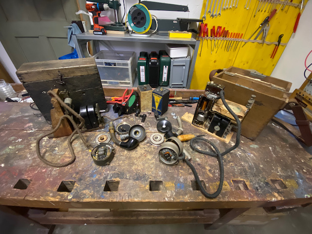
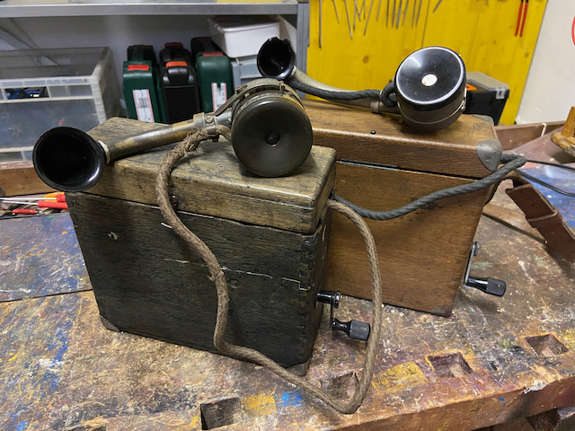
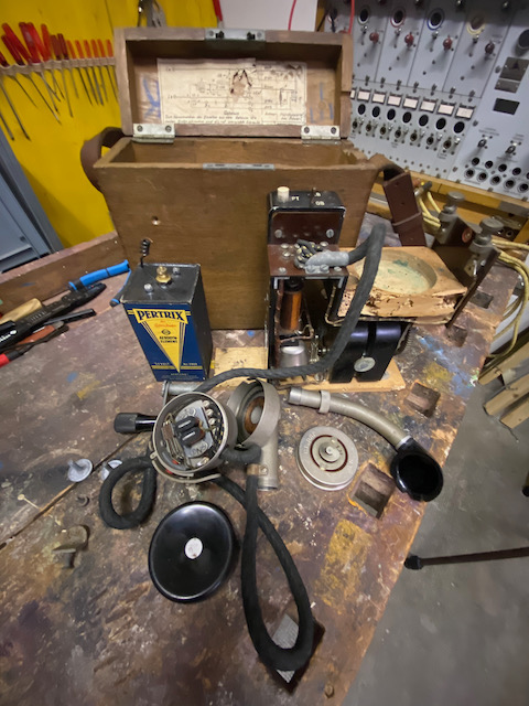
Left model "1907", right "1933".
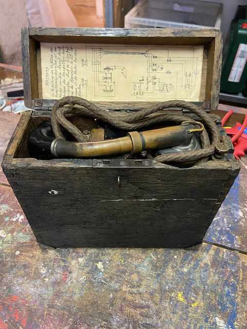
Ready to use.
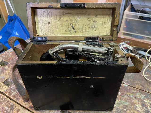
Ready for transport.
![]()
Diagram model "1907".
(Selfmade repro, original was missing in that instrument as lid has been replaced once)
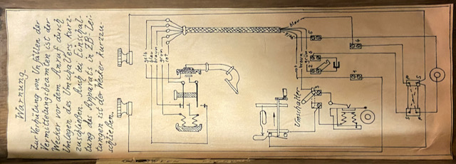
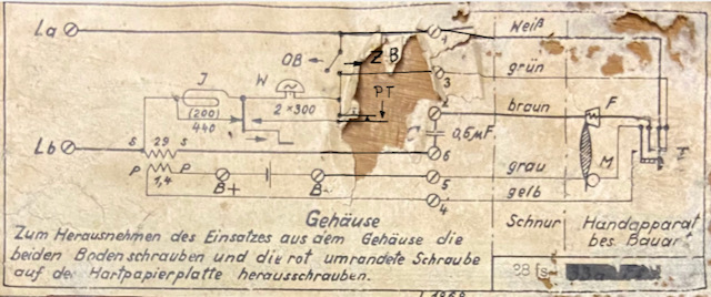
Diagram model "1933".
("fixed" the missing parts).
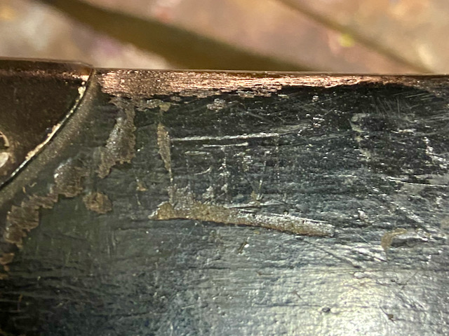
The diagram seems to name the device originally 33a fs, therefore I call it model "1933".
Later this has been covered by a black bar (probably stamped) and changed to 38 fs (fs = Fernsprecher, maybe?).
The capacitor in this device is from 1938, either the device has been built or refurbished in 1938.
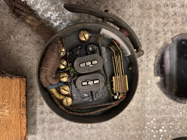
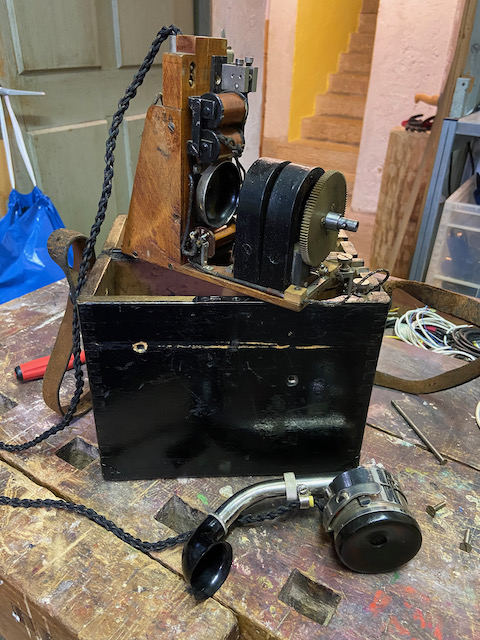
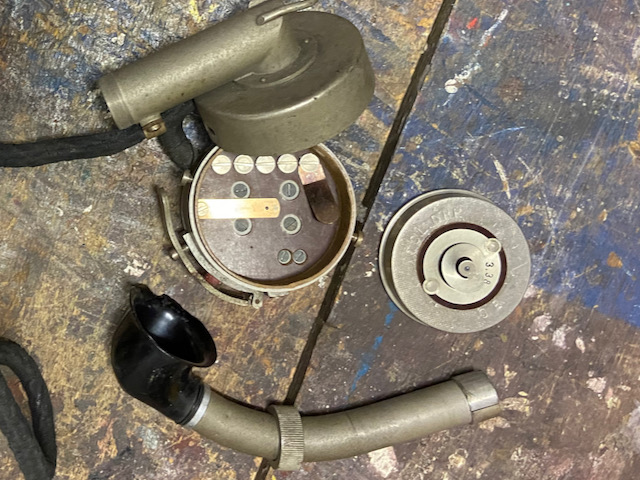
"1907" disassembled at restoration time.
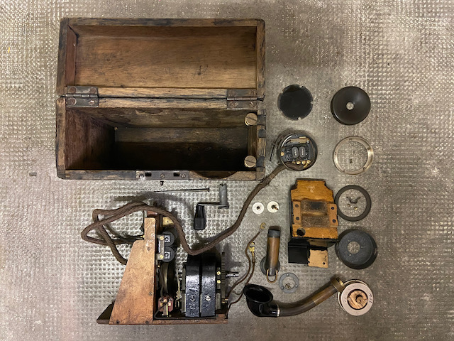
Compact 2-bar magneto, behind it on top the DC ringer and below the coil.
The coil looks like it was replaced some time.
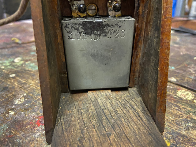
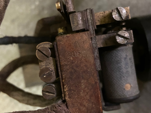
The capacitor is put at the inner edge of the battery compartment.
This capacitor was replaced some time, probably in the year of make of the capacitor (1923) or a little bit later.
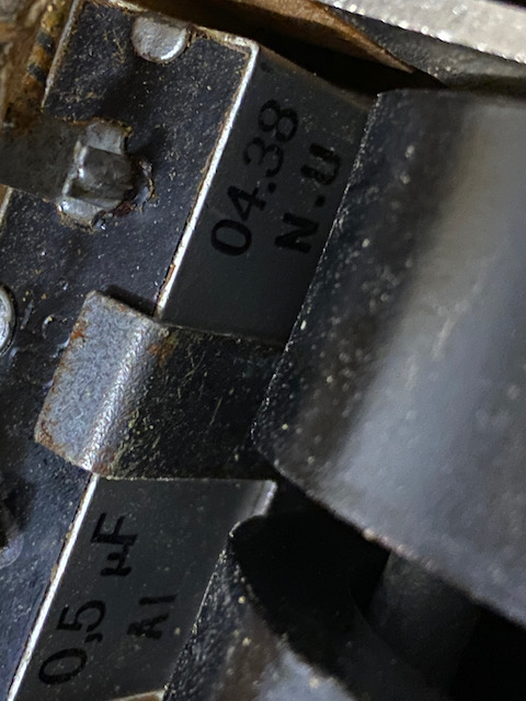
The "Mix & Genest" made capacitor is the wrong size, it should have been originally a 0,5uF.
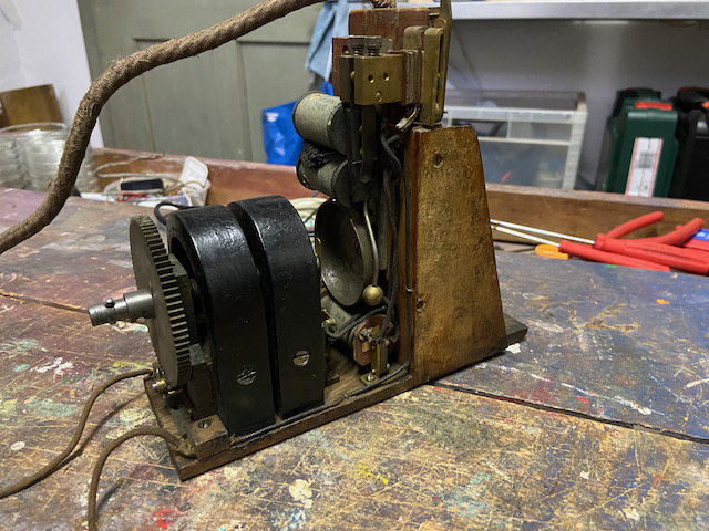
Model "1907" TX side.
The ZB (CB) type TX element has a handmarked date 1921 and 1922, made by C. Lorenz.
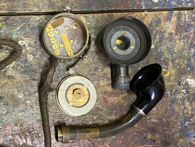
Model "1907" RX side.
Not a lot of space in there.
The left switch reeds change between ringer and RX circuit and the right switch reed connects the TX circuit.
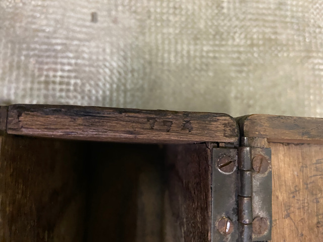
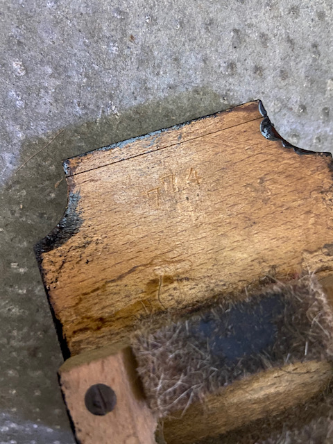
This model "1907" has the serial number 774, case, magneto lid and body are marked.
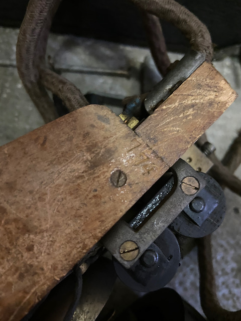
"W Ausg." = "Wecker ausgeschaltet" (Ringer turned off).
Current switch lever position is on.
On the left the bridge which shortens the capacitor.
Remove this bridge when connecting to LB networks with dc supervision end of call signalling ("Selbsttätiges Schlusszeichen").
Handset stored.
Another not yet restored model 1907.
On this other model the lid is still original and marked RTV (Reichstelegraphenverwaltung) on the outside.
Handset stored.
Still the original diagram on this one.
The note says "Postamt Arnsberg Störstelle Kuhlmann".
Kuhlmann was probably the name of the technician using the instrument.
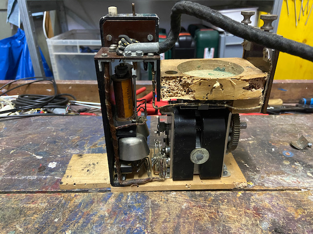
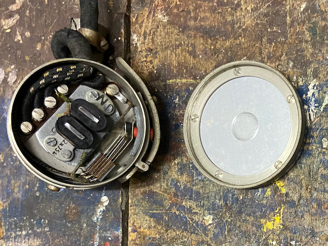
Model "1933" disassembled.
This one had a serious woodworm issue, fixed by baking all wood parts in the oven for some hours.
Compact 2-bar magneto, coil, AC ringer.
The ringer is made by F. Schuchardt.
On top left the white test button, on the right the lever switch "OB" - "ZB".
Capacitor made in 1938.
TX element also made in 1938.
RX side, basically the same setup as in model "1907".
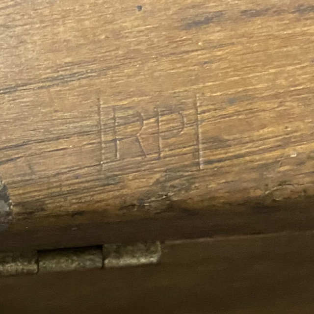
The lid is stamped "RP" (Reichspost).
Model "1933" handset stored.
Creative Commons Attribution-ShareAlike 4.0 International License