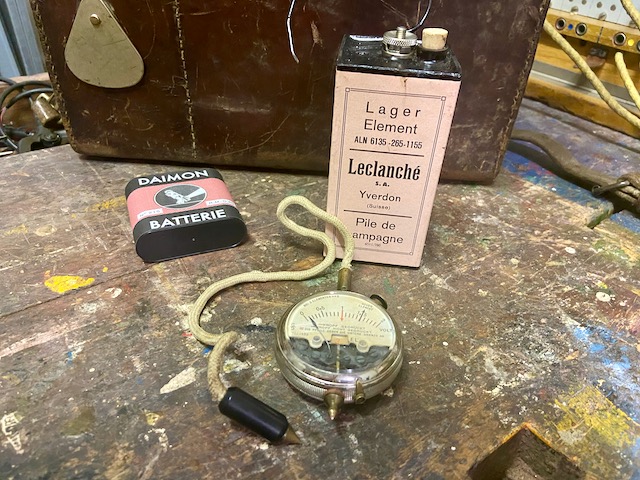
This is the german army "Elementprüfer neuer Art" introduced in 1916. This specimen has been made by Siemens & Halske. Unfortunately the leather box is missing.
V.P.K. June 1916.
Description of the element tester of the new type.
S 211a
Telegram words
New type of element tester ... prüna
Empty container ... beprüna
New type of element tester in the container ... prübena
1. The element tester is used to measure the voltage and internal resistance of individual elements and batteries consisting of 3 elements, as well as pocket lamp batteries of 4.5 volts.
2. The element tester has the shape of a pocket watch (Fig. 1). To test an element, the switch located on the back (Fig. 2) is set to "1 element"; at the same time, the number 1 is visible in red under the scale on the front. The tester is placed on the carbon pole of the element to be measured with a tip attached below. The plug, which is connected to the tester by a cord, is used to touch the zinc pole wire or, in the case of batteries, the carbon pole of the following element. The tester then displays the voltage.
3. To test a battery of 3 elements or a flashlight battery, the switch on the back (Fig. 2) is set to "3 elements", at the same time the number 3 is visible in red under the scale on the front. The tester is now placed with the tip attached below on the carbon pole of the first element of the battery to be measured. With the plug, which is connected to the tester by a cord, you touch the zinc pole wire of the 3rd element. To obtain the voltage of the battery, one must multiply the voltage indicated by the tester by 3, also a simple reading is sufficient, since it gives the average voltage for each element.
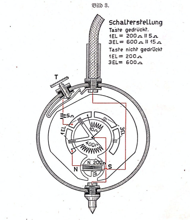
4. Since the resistance of the circuit through which the battery current has to flow in telephone sets is only low, the internal resistance of the elements is very important here. The element tester is therefore set up in such a way that a shunt of about 5 ohms - with the setting "1 element" - can be switched on by pressing the T key, while the tester himself has resistance of 200 ohms. With the setting "3 elements" a shunt of about 15 ohms is switched on, while the tester himself has a resistance of 600 ohms. When the shunt is switched on, the terminal voltage drops according to the internal resistance of the element or the battery to be measured.
5. That the internal resistance of the element or the battery does not have to be calculated from the measurement each time, a red line on the dial shows how far the terminal voltage may drop when the shunt is switched on if the element or the battery should still be useful for telephone operation.
6. The reading must take place immediately after pressing the T key because, due to the low resistance of the tester when the key is pressed, polarization phenomena quickly occur in the element or in the battery, which cause the pointer to drop further.
7. The internal equipment of the examiner is shown in Figure 3. A permanent magnet encloses a cylindrical, fixed iron core between its poles N and S; around this a coil of 200 ohm resistance is placed on a rotatable copper frame that carries the pointer. If a current flows through the coil, poles N and S are created in the iron core, which rotate the coil and thus the pointer. The copper frame has a dampening effect, i.e. That is, it inhibits the movements of the pointer so that it does not oscillate for a long time, but rather sets itself to the correct value.
8. The instructions for use for the tester are on the dial. It is always important to ensure that the switch is set to "3 elements" in the idle state. After measuring with "1 element", the switch must therefore always be switched back to "3 elements".
9. The instrument is carried in a leather case. The weight of the element tester is approximately 0.2 kg, with the container 0.4 kg.
V.P.K. Juni 1916.
Beschreibung des Elementprüfers neuer Art.
S 211a
Telegrammworte
Elementprüfer neuer Art ... prüna
Leerer Behälter ... beprüna
Elementprüfer neuer Art im Behälter ... prübena
1. Der Elementprüfer dient zum Messen der Spannung und des inneren Widerstandes einzelner Elemente und Batterien, bestehend aus 3 Elementen, sowie von Taschenlampenbatterien von 4,5 Volt Spannung.
2. Der Elementprüfer hat äußerlich die Form einer Taschenuhr (Bild 1). Zur Prüfung eines Elementes wird die auf der Rückseite (Bild 2) befindliche Umschaltevorrichtung auf „1 Element" eingestellt, gleichzeitig wird unter der Meßskala der Vorderseite die Zahl 1 in roter Schrift sichtbar. Der Prüfer wird mit einer unten angebrachten Spitze auf den Kohlenpol des zu messenden Elementes aufgesetzt. Mit dem Stöpsel, der durch eine Leitungsschnur mit dem Prüfer Verbindung hat, berührt man den Zinkpoldraht oder bei Batterien den Kohlenpol des folgenden Elementes. Der Prüfer zeigt dann die Spannung in Volt an.
3. Zur Prüfung einer Batterie von 3 Elementen oder einer Taschenlampenbatterie wird die auf der Rückseite (Bild 2) befindliche Umschaltevorrichtung auf "3 Elemente" eingestellt, gleichzeitig wird unter der Meßskala auf der Vorderseite die Zahl 3 in roter Schrift sichtbar. Der Prüfer wird nun mit der unten angebrachten Spitze auf den Kohlenpol des ersten Elementes der zu messenden Batterie aufgesetzt. Mit dem Stöpsel, der durch eine Leitungsschnur mit dem Prüfer in Verbindung steht, berührt man den Zinkpoldraht des 3. Elementes. Um die Spannung der Batterie zu erhalten, muß man die vom Prüfer in Volt angezeigte Spannung mit 3 multiplizieren, doch genügt auch die einfache Ablesung, da sich aus ihr die durchschnittliche Spannung für jedes Element ergibt.
4. Da der Widerstand des Stromkreises, den der Batteriestrom bei Fernsprechapparaten zu durchfließen hat, nur gering ist, so kommt hierbei der innere Widerstand der Elemente sehr in Betracht. Der Elementprüfer ist daher so eingerichtet, daß durch Drücken einer Taste T bei Einstellung "1 Element" ein Nebenschluß von etwa 5 Ohm eingeschaltet werden kann, während der Prüfer selbst einen Widerstand von 200 Ohm hat. Bei Einstellung "3 Elemente" wird ein Nebenschluß von etwa 15 Ohm eingeschaltet, während der Prüfer selbst einen Widerstand von 600 Ohm hat. Durch das Einschalten des Nebenschlusses fällt die Klemmenspannung entsprechend dem inneren Widerstand des zu messenden Elementes bzw. der Batterie.
5. Damit nun nicht jedesmal erst aus der Messung der innere Widerstand des Elementes bzw. der Batterie berechnet werden muß, ist auf dem Zifferblatt durch einen roten Strich angegeben, wie weit die Klemmenspannung bei eingeschaltetem Nebenschluß sinken darf, wenn das Element bzw. die Batterie für den Fernsprechbetrieb noch brauchbar sein soll.
6. Die Ablesung muß sofort nach dem Drücken der Taste T erfolgen, weil infolge des geringen Widerstandes des Prüfers bei gedrückter Taste rasch Polarisationserscheinungen im Element bzw. in der Batterie eintreten, die ein weiteres Sinken des Zeigers zur Folge haben.
7. Die innere Einrichtung des Prüfers zeigt Bild 3. Ein Dauermagnet schließt zwischen seinen Polen N und S einen walzenförmigen feststehenden Eisenkern ein; um diesen ist eine Spule von 200 Ohm Widerstand auf einen drehbaren Kupferrahmen gelegt, der den Zeiger trägt. Fließt durch die Spule ein Strom, so entstehen in dem Eisenkern Pole N und S, welche die Spule und somit den Zeiger drehen. Der Kupferrahmen wirkt dabei dämpfend, d. h., er hemmt die Bewegungen des Zeigers, so daß dieser nicht lange pendelt, sondern sich gleich auf den richtigen Wert einstellt.
8. Die Gebrauchsanweisung für den Prüfer steht auf dem Zifferblatt. Es ist stets darauf zu achten, daß im Ruhezustande der Umschalter auf "3 Elemente" steht. Nach Messung mit "1 Element" ist daher der Schalter stets wieder auf "3 Elemente" umzustellen.
9. Der Prüfer wird in einem Lederbehälter mitgeführt. Das Gewicht des Elementprüfers beträgt etwa 0,2 kg, mit Behälter 0,4 kg.
The Elementprüfer with an original Swiss Leclanché inert element (activated) and a 4,5V flashlight battery (self made Daimon repro label).
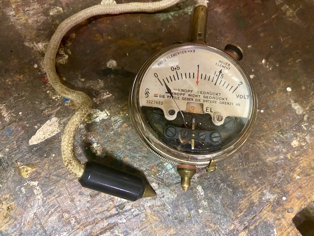
Front view.
Set to "3 Elements".
Back view.
Set to "3 Elements".
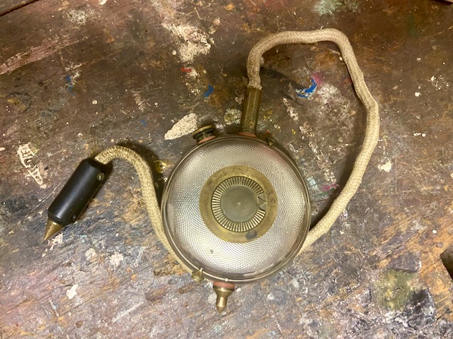
Bild 1.
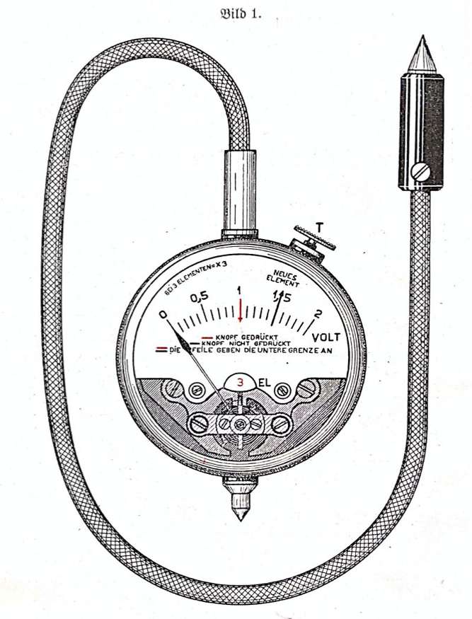
Bild 2.
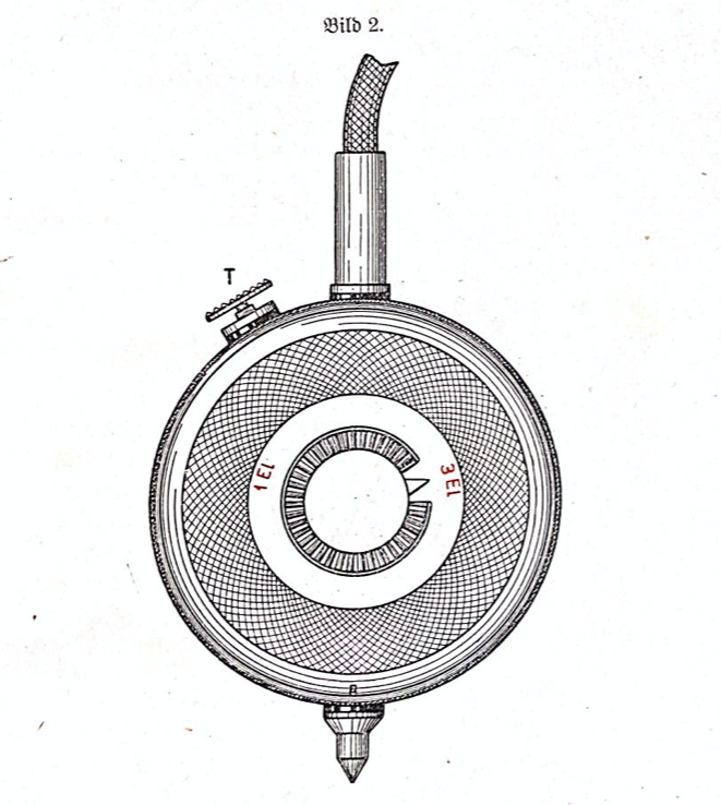
Bild 3.
Creative Commons Attribution-ShareAlike 4.0 International License