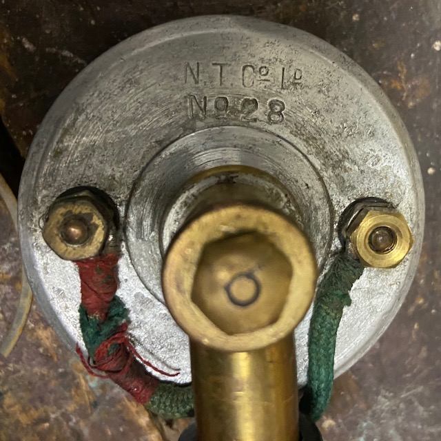
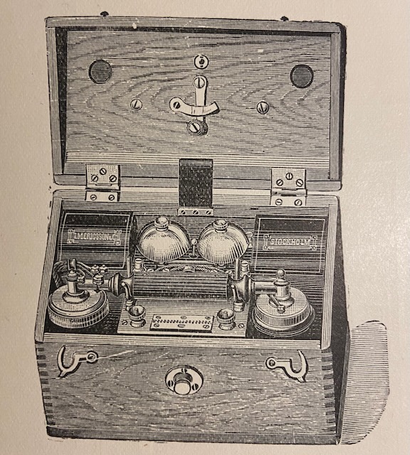
This instrument is Ericsson designed and probably also manufactured. It corresponds to an Ericsson No. 390 (Catalog 1902) or MB100 (Catalog 1910), and an N.T.C. B38 (Catalog 1903) [1] [2]. The handset is marked N.T.Co. Ltd. No. 28. N.T.Co. stands for the British National telephone company, the leading independent company introducing telephony to England in the late 19th century [5]. N.T.Co. was an important Ericsson customer and later helped to start the Ericsson manufacturing in Britain. N.T.Co. was taken over by the governments G.P.O. (General post office) in 1912. The same Ericsson model was also used for the first British army field instrument, the Telephone Set C Mk I [7].
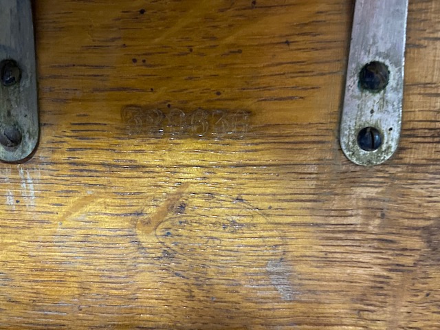
When assuming that this instrument was made in Sweden the serial number of #329636 marked inside the lid would point to a manufacturing year of 1902 [4]. Beneath the serial number there is also a not very legible stamp indicating G.P.O. approved. I assume this instrument was used as PTT lineman's field instrument in Britain.
From the Ericsson Catalog 1910 for portable telephone instrument MB100: This instrument consists of: a polished oak case with carrying handle, containing generator, magneto bell, microtelephone with waterproof cord and indiarubber mouthpiece with nickelplated metal mountings (can be supplied with a celluloid mouthpiece if required), 2 dry cells type RK 190 (Old Cat. No. 600) lightningarrester & terminals for line and earth.
Sawtooth lightning arrestor with short circuit peg-holes.
If the instrument is set in series into a single line setup with earth return the peg can be used to either shorten the line from L1 to L2 and thus deactivate the instrument and close the line for other instruments, or switch the instrument's L1 or L2 side to the earth return to connect the instrument to either of these sides. Update 20220505: Peg is described to be used to a) test bell (put Peg in short-circuit hole between L1 and L2) and b) to put L2 to earth when using earth return connection [7].
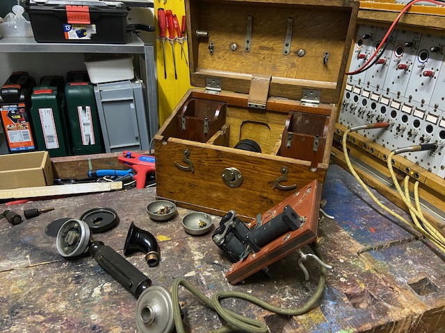
Disassembled.
Serial number #329636.
Below that a stamp indicating G.P.O. approved.
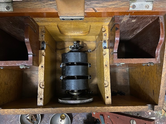
Mounted to the bottom of the main box the three bar magneto with the typical Ericsson centrifugal force switch.
The magneto is of self shortening type (when not used the centrifugal force switch is closed and the magneto is shorted out of the circuit).
To the left and right back the battery compartments.
The battery compartments were originally covered by metallic lids not present here.
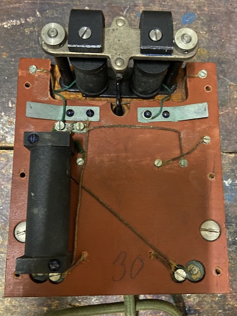
Bottom of the main board.
Coil and ringer.
The two contact strips connect to the generator when the board is mounted.
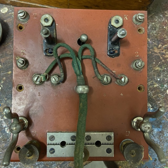
At the top of the main board topside are the connectors for two 1,5V batteries in series (K, Z).
In the middle the handset connectors M (1, 2) and T (3, 4).
At the bottom the Line (L1, L2) and earth connectors and the sawtooth lightning arrestor.
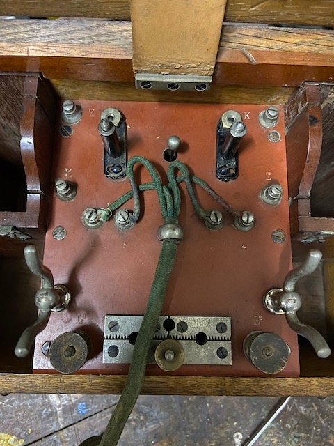
The main board mounted again on top of the magneto.
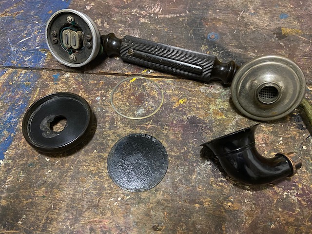
The handset with open RX segment and removed mouthpiece. The earpiece lid is slightly damaged.
The brass parts nickel plating is mostly gone.
On the P.T.T. lever imprinted: Press this while speaking.
RX open front.
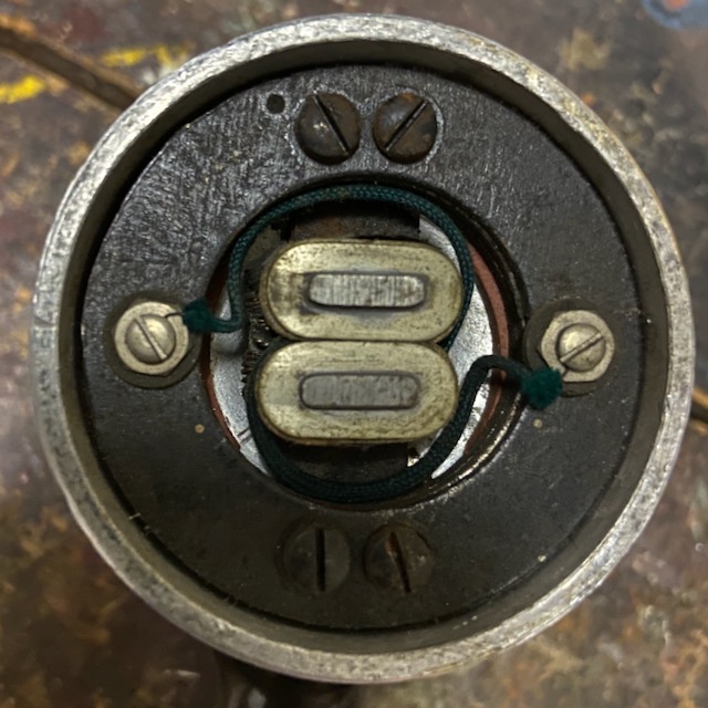
On the RX back the brand indication N.T.Co. Ltd., No. 28.
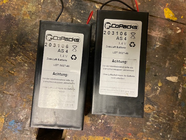
Modern dry batteries of traditional field phone battery size 57 x 57 x 125 mm (IEC S4, Copacks is a brand from german akkuplanet).
Original batteries from Ericsson were of type 600 (Catalogs pre 1910), later called RK 190 (Catalog 1910+).
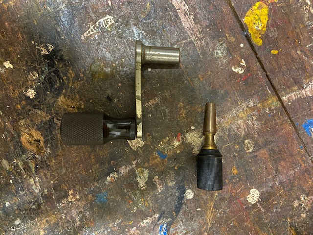
The magneto crank handle and the lightning arrestor short circuit peg.
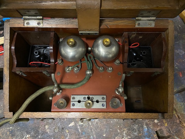
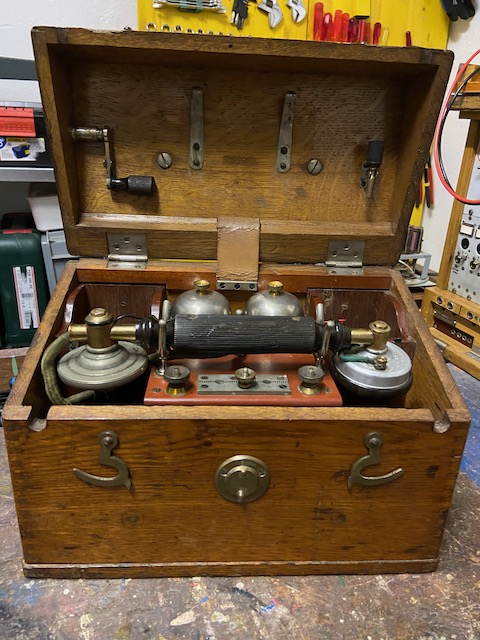
Bells and batteries mounted.
The battery boxes have grooves put the battery cables through.
The batteries are connected in series (the K and Z connectors on the back are connected below the board).
the battery box metal lids unfortunately are missing.
At the front of the battery box the latches for this lids are visible.
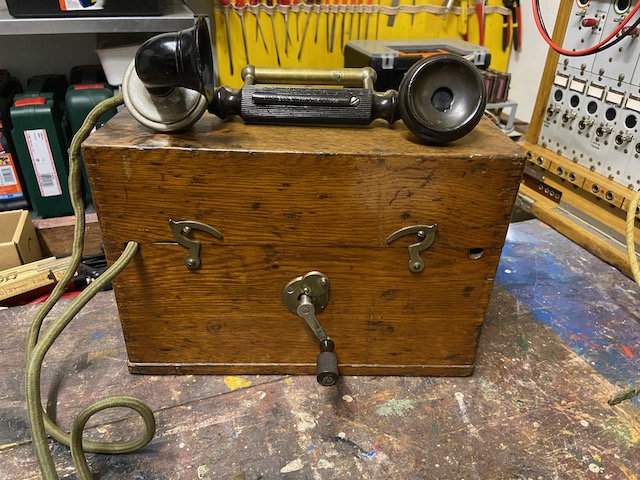
Ready for use.
The box has openings for the handset and the line cables.
The crank handle is mounted to the front of the box (on typical later fieldphones cranks are mostly mounted from the side).
Handset and accessories (Crank handle, short circuit peg) stored.
Not visible in this picture, to store the handset the mouthpiece has to be turned 90 degrees.
Instrument ready for transport.
A beautiful box on it's own.
![]()
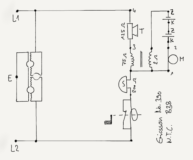
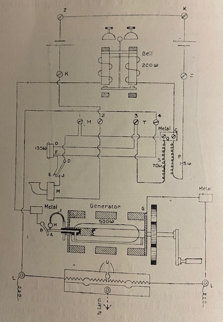
Electrical diagram (self made).
C. Mk. I. [7].
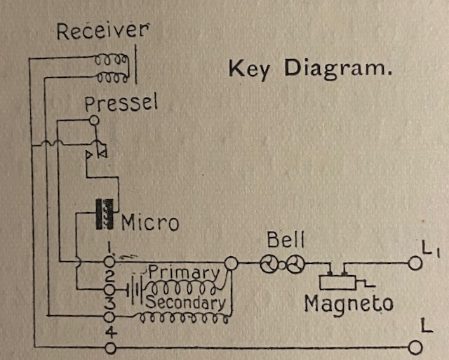
C. Mk. I. Wiring diagram [7].
C. Mk. I. Electrical diagram [7].
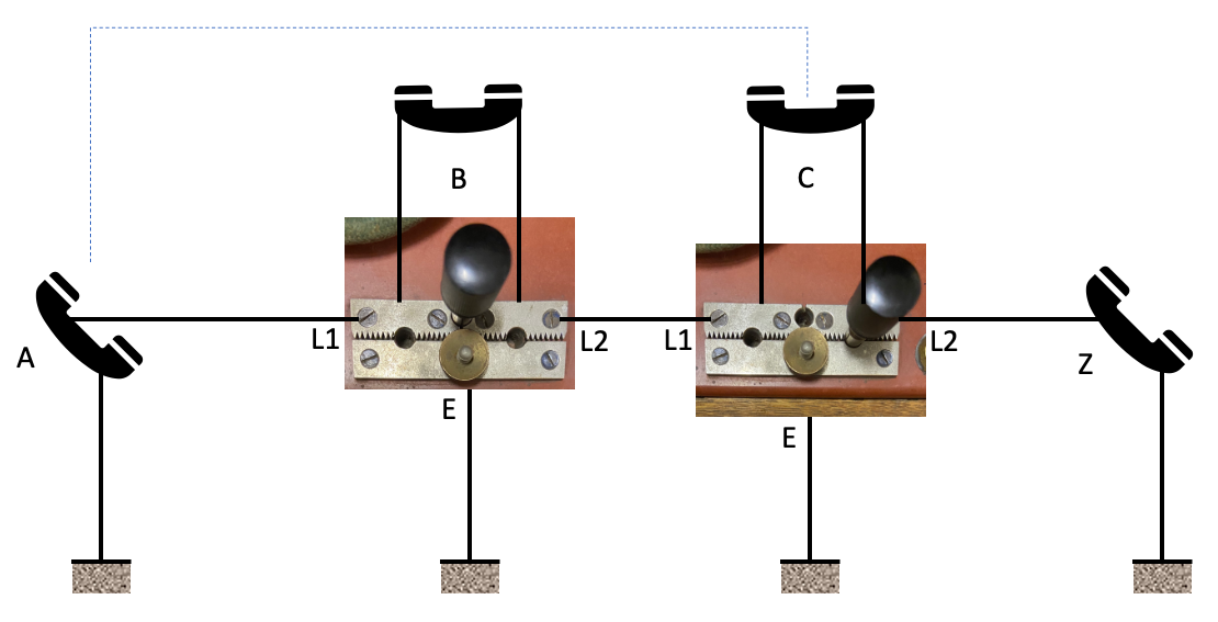
My understanding what the short circuit peg can be used for. If anybody knows if that was the idea or this is wrong let me know.
Instruments B and C are in series between the end stations A and Z on a single line with earth return.
Instrument B has closed the line and is disabled.
Instrument C has connected L2 to ground and therefore is connected in direction of A and disconnected in direction of Z.
Instrument C and A can communicate.
Update 20220505: That was an interesting idea of mine but what is described in [7] makes probably more sense: Used to test local bell (Peg between L1 and L2) or to put L2 to earth when using earth return line connection.
Creative Commons Attribution-ShareAlike 4.0 International License