Muchas Gracias to Ezesar for donating the device and all the additional information.
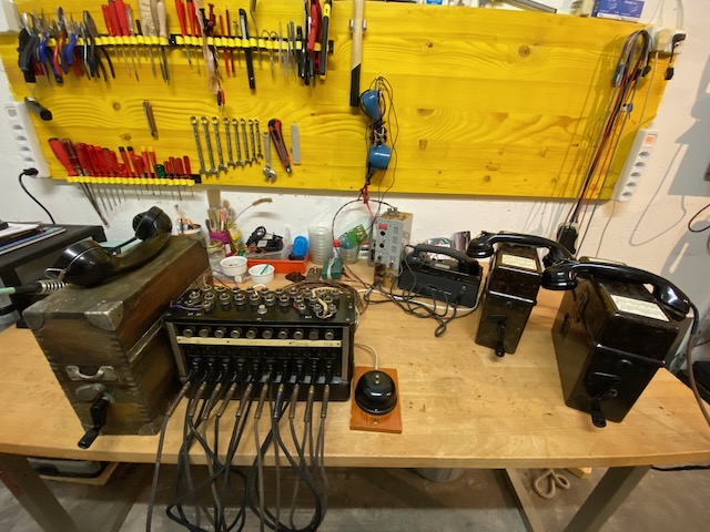
This is a compact and highly portable 10-line switchboard "Centralita Telefonica J.T.E. C-3020" (J.T.E.: "Jefatura de transmisiones del ejercito", army transmission headquarters), manufactured by Standard Eléctrica S.A. for the Spanish military in the early 1940s. The device bears no label indicating the manufacturer or production year. It was in use by the Spanish military until the eighties.
Electrically and mechanically, it is nearly identical to the German "Kleiner Klappenschrank zu 10 Leitungen" (~1933), but it is even smaller and lighter. The case is made of sheet metal, while the chassis is mounted beneath a top panel made of a Bakelite-like material.
To operate the switchboard, an external operator set (e.g., the C-30101) and optionally an external ringer with battery are required. It is a monocord-type switchboard. Lines are selected using individual buttons, and a central reset button is provided. Incoming calls are indicated by relay flaps, which also trigger the external ringer if connected. [1]
From "Instruccion de transmisiones" [2] (translated from spanish):
Once the switchboard has been checked, it is installed as follows: The folded top cover is placed behind it, and the switchboard operator's telephone is placed on top of the cover. The cords are placed through the holes in the bottom of the case, and the plugs are inserted into their sockets. The cords should not be tangled, as otherwise the plugs would end up in the wrong sockets, and the switchboard would not function properly. The holding strip is raised to release the call indicators.
Once the lines and the switchboard operator's telephone are connected, the switchboard is ready to operate. The switchboard operator can use the holding strip to write down the names or call signs of the subscribers with a pencil, thus establishing connections more quickly and with fewer errors.
The operation of this switchboard is very simple: When a subscriber calls the switchboard, the switchboard operator will see the call indicator fall. To speak to them, the operator simply presses the corresponding listening switch. When the switchboard operator wants to call a subscriber, they must press the listening switch on that line and place the call using the operator telephone. For two subscribers to talk to each other, the operator must insert the plug of one line into the other line jack. If the link is poor, it is best to try the same with the other plug. Thus, if subscribers 3 and 7 want to talk to each other, the switchboard operator must insert plug 3 into the link jack of 7, and, if necessary, plug 7 into the link jack of 3.
The switchboard operator can listen to any conversation between a pair of subscribers by pressing the listen switch on one of them. The central operator can connect groups of more than two subscribers. For example, if the first four wish to talk to each other, he will insert plug 1 into the link jack of 2; the plug from this into jack 3, and so on until they reach plug 4. The central operator must be careful when handling the plugs: they must be held by their black part. If they are pulled by the cord, the internal connections will eventually come loose, rendering the plug useless.
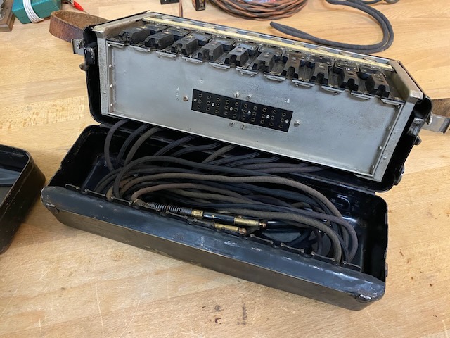
Completely modular, no soldering required to replace cords and complete line modules with their relays and jacks.
Disassembled.
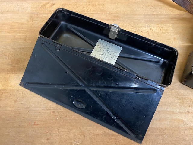
Diagram (inside the removable top lid).
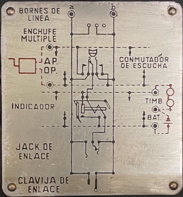
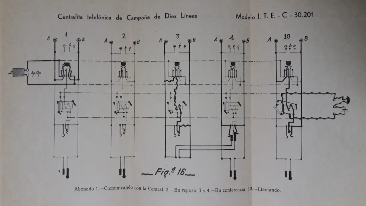
Diagram from [1] indicating the different operational modes.
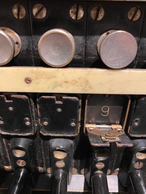
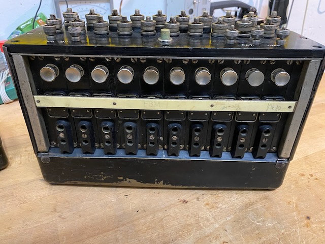
Line 1: connected to switchboard, Line 2: Idle, Line 3 and 4: connected, Line 10: incoming call.
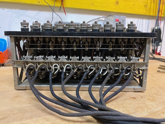
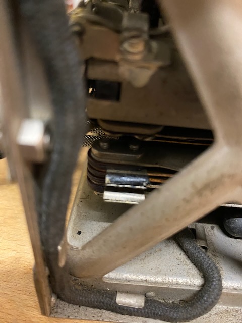
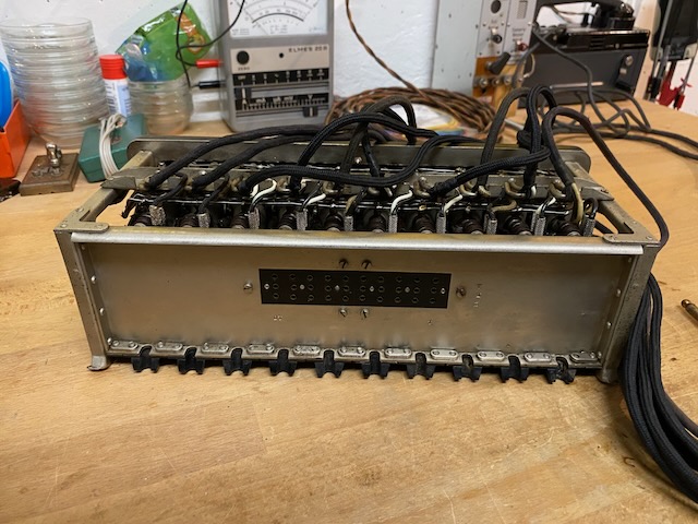
Chassis removed from the metal box, from the back.
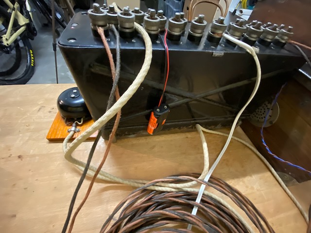
Detail of the sockets to connect the line cords, with a cord removed.
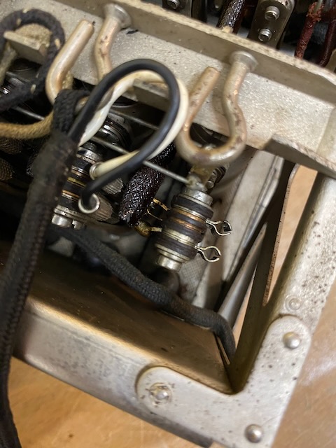
Detail of the sockets to connect the line cords, with a cord removed.
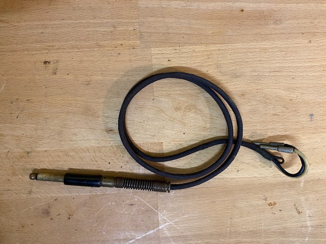
The removed cord.
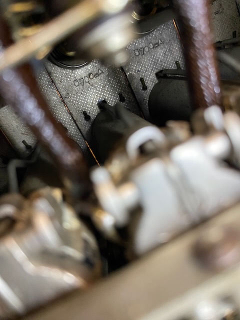
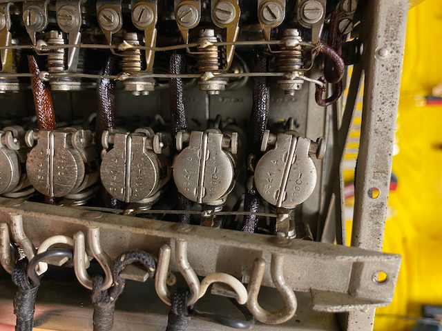
On the back of the faceplates there is a product number: "5700_A".
This type of product numbers were typically used by all European BTMC/ITT/Standard Electric related companies.
On the relay there is a product number: "5541 A" and the indication 1000 Ohm.
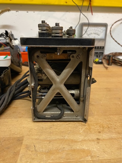
Chassis from the side.
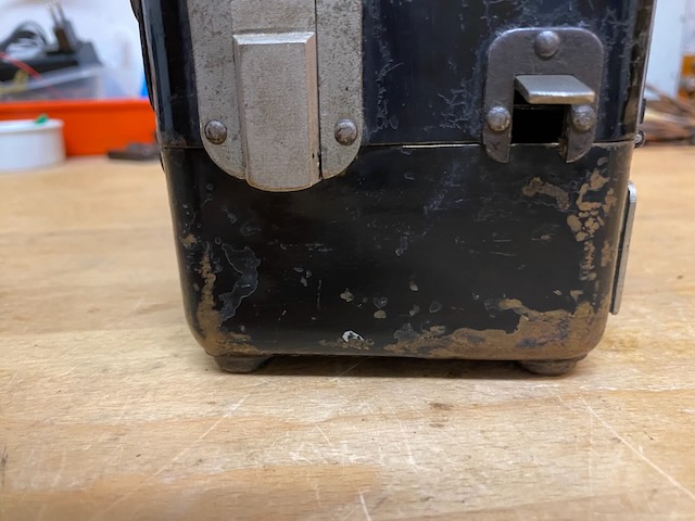
From the bottom.
On the bottom a multiple socket.
The empty box.
![]()
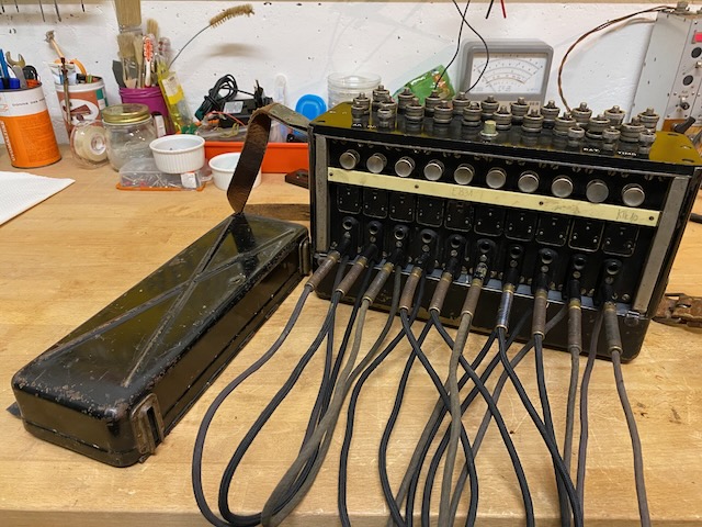
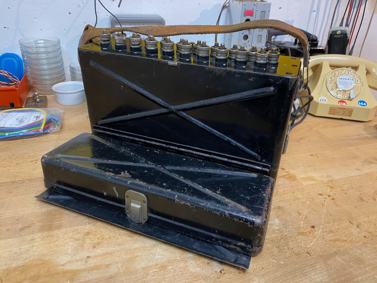
Assembled, ready to use.
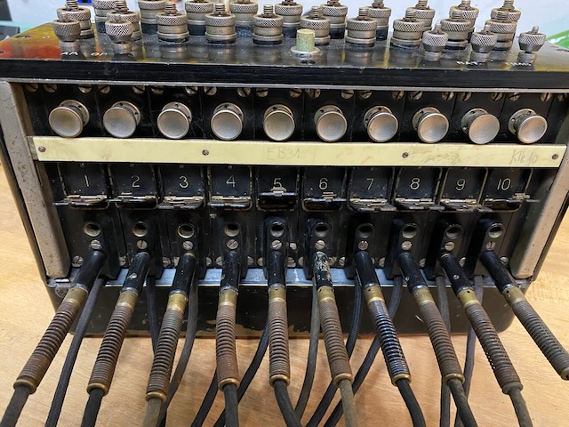
Behind the relays flaps the lines are numbered.
From the top.
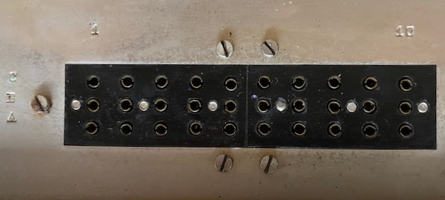
10x a/b, AP.OP is for the operator instrument connection and BAT./TIMB for the external ringer and its battery.
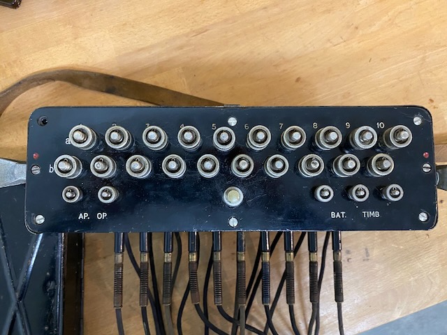
Line binding posts detail.
Relay flap detail.
Small lid for passing the multiple cable if used.
These brackets allow to attach the top lid behind the bottom shelf to give the device more tilting stability.
The brackets fit into each other.
The top lid mounted to the back of the bottom shelf to give the device more tilting stability.
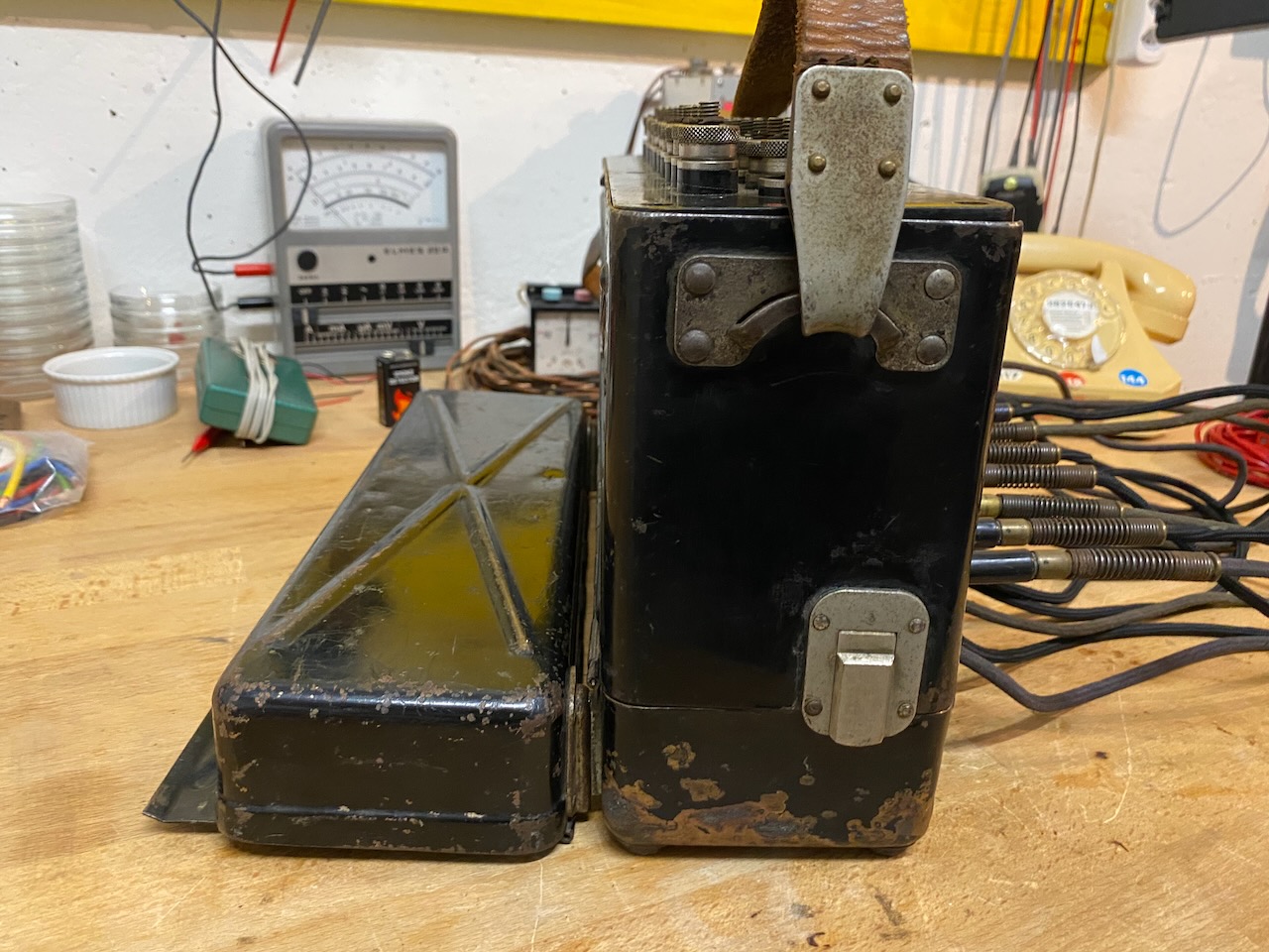
The top lid mounted to the back of the bottom shelf to give the device more tilting stability.
Cords stored in bottom shelf.
Flap retainer moved over flaps for transport.
The flap retainer can be used as line label.
The fron and top lid assembly, with the electrical diagram inside top lid.
Ready for transport.
![]()
From the back.
![]()
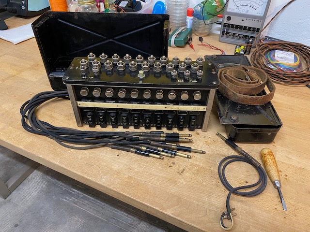
Setup used for the demo Video.
Ringer battery, "modern version".
Creative Commons Attribution-ShareAlike 4.0 International License