
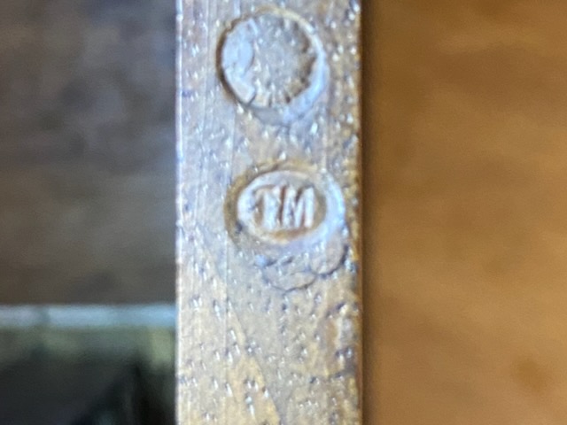
The "TM" mark ("Télégraphie Militaire") indicates that this portable desk telephone was used by the French army.
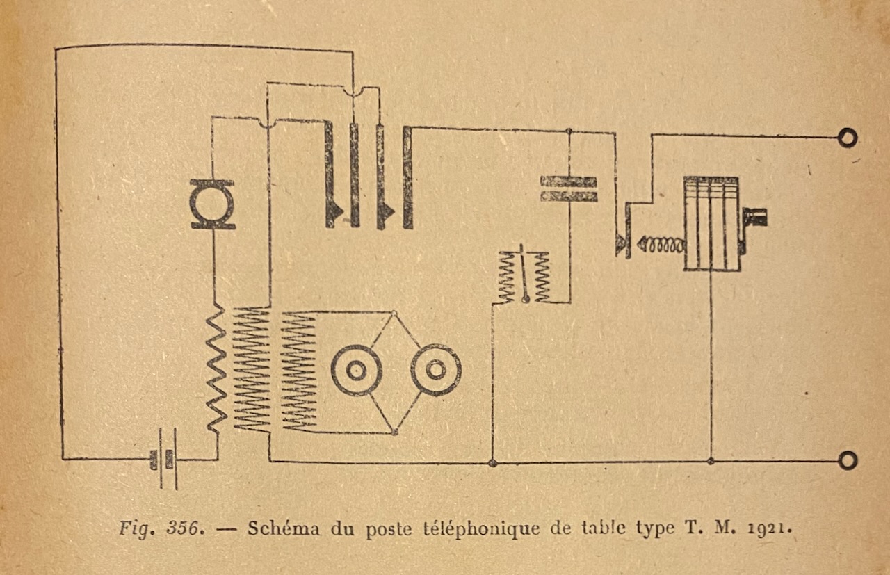
Another clue is its appearance in a transmission course document from the "Ecole Militaire d'Artillerie," though it is not explicitly mentioned [1].
Based on the components and technology used, the design and manufacturing date is estimated to be between 1915 and 1925.
"Poste Téléphonique de Table, T.M. Modèle 1921" [2].
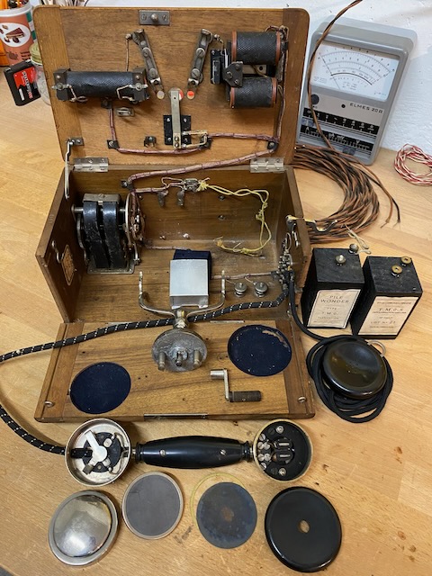
This telephone set includes, all in one box: A magnetic caller, a polarized buzzer, two T.M. No. 0 batteries, a handset, an additional receiver, and a movable fork mount. This telephone is designed for use on both central and local battery networks. [...] In the transport position, the handset, the fork mount, the additional receiver and its support hook, as well as the magneto crank, are inside the case. [...] Observations: The three-winding induction coil is designed to prevent the line current from the central battery from demagnetising the permanent magnets of the receivers. These are, in fact, placed in a separate circuit. However, this arrangement is detrimental to hearing, which is noticeably weakened. To avoid the aforementioned problem of receiver demagnetisation, it would suffice, in the usual wiring of the receivers to the line circuit, to take into account the polarity of the current from the central battery. [...]
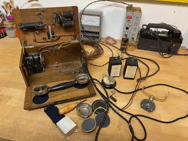
The telephone features a detachable hook switch fork and a dismountable magneto crank lever. Both the hook switch fork and crank lever, along with the permanently connected handset and headset, can be stored inside the main wooden box, which is equipped with a leather handle for easy transport.
The circuit design supports connections to both LB and CB lines; however, on CB lines, the microphone requires power from the local battery. Notably, the coil has an uncommon three-winding configuration, providing galvanic separation between the telephone receiver and the line circuits.
Dismountable hookswitch fork which also disconnects the battery.
The only source known to me for this device is that it It is imaged as example of a device with a fork type hook switch in a transmission course document from the "Ecole Militaire d'Artillerie" (1930) [1].

Disassembled.
The electrical setup is quite special, using a three winding coil and galvanically separating the rx (and tx) circuit from the line circuit [2].
On the left box wall top the device is marked with "TM" (from "Télégraphie Militaire").
The handset is a standard construction with a fix RX setup and a modular TX capsule.
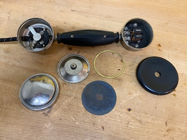
Handset TX side detail.
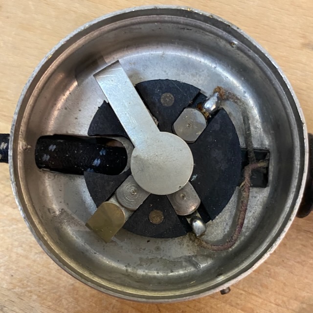
Handset RX side detail.
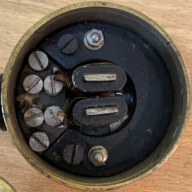
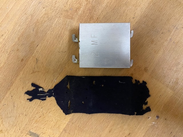
The capacitor is easy removable (contacts screwed on not soldered).
It is covered by a piece of felt.
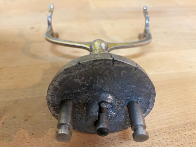
The fork assembly from the bottom.
The body is zinc die-cast and heavily affected by zinc pest.
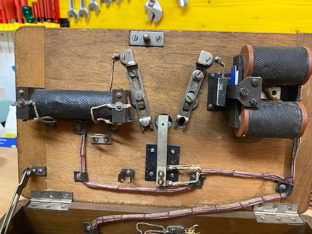
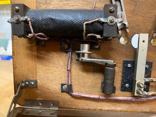
The three winding coil, clapper type polarised ringer and the hook switch mechanism are mounted to the top lid inside.
The two sliding brackets fix the hookswitch assembly when fitted and also close the battery circuit.
(As the hook switch is zinc pest affected it does not fit anymore with both bolts mounted, the right one is removed).
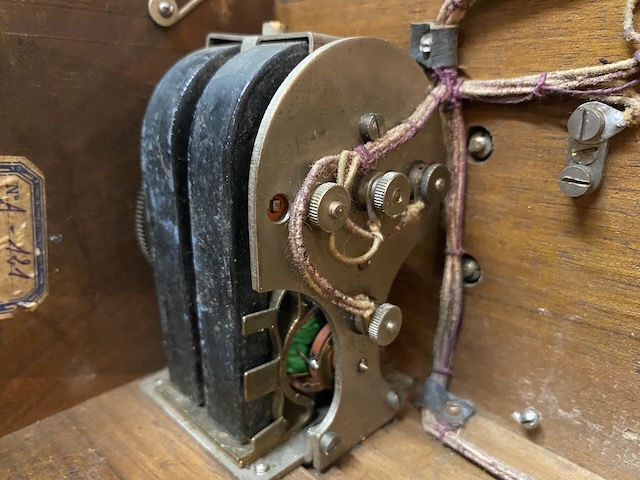
Magneto with two magnets.
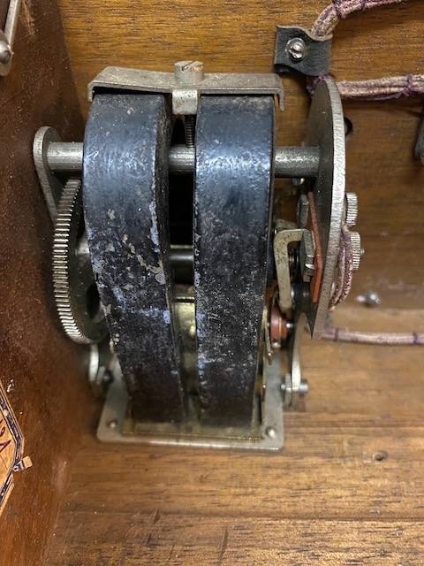
All magneto connections are also screwed on and not soldered.
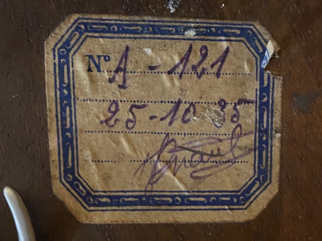
A paper label is glued to the box inside, maybe an inventory or repair mark with what is most probably a calendar date of 25. 10. 1935.
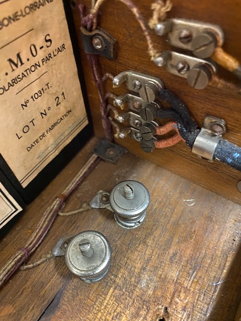
Line binding posts and handset and headset connections.
All parts neatly arranged.
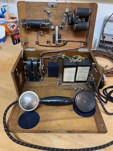
All parts mounted.
The device probably used TM-0 type elements.
These are self TM-0 recreations.
Front lid closed.
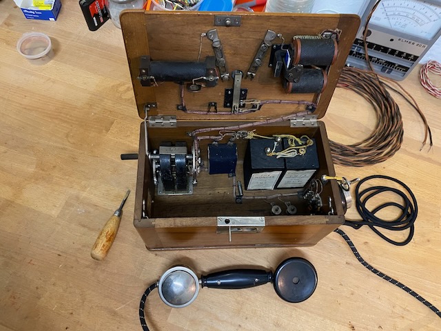
Ready to use.
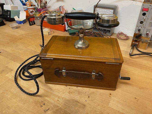
All parts packed into box.
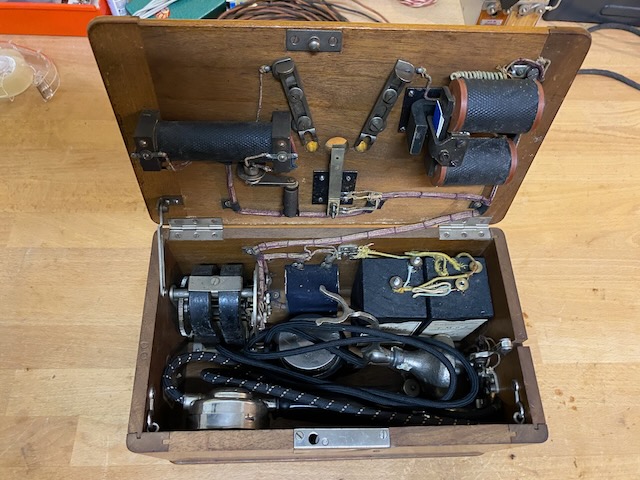
There are two brackets beneath the coil which take up the magneto crank handle.
Ready for transport.
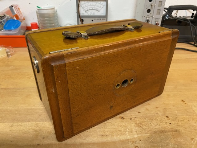
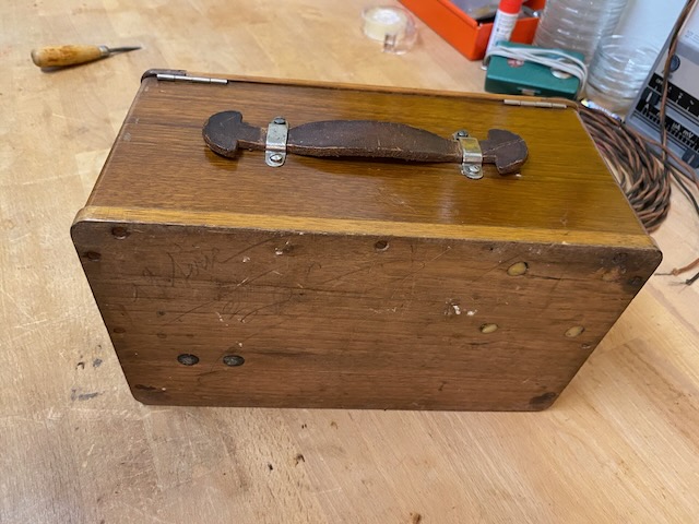
The back respectively bottom of the box.
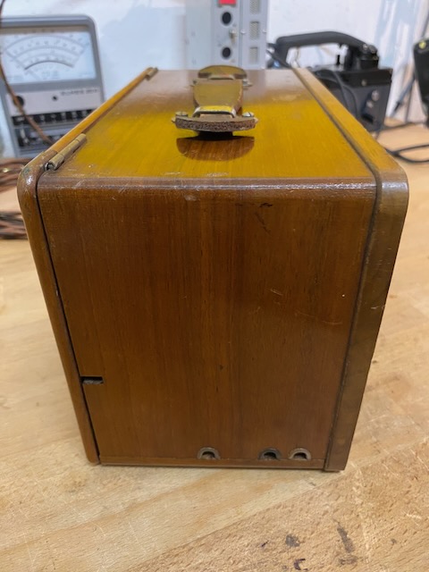
Box from the right.
At the bottom edge the openings for the handset and headset cords and the line.
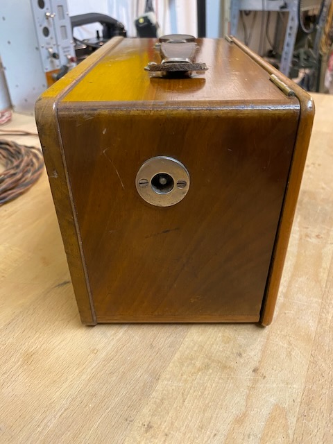
Box from the right with the magneto crank handle opening.
Creative Commons Attribution-ShareAlike 4.0 International License