Find more details on German field telephone history on the German Field Telephones Timeline.
The "Eiserner Armeefernsprecher" is the 1913 successor [5] [6] to the original 1905 "Armeefernsprecher", later referred to as the "Armeefernsprecher alter Art" ("Army Telephone, Old Type"). The electrical setup and functionality remain identical to the 1905 model, but the 1913 version is constructed from painted sheet metal instead of aluminum. Additionally, the talk switch has been modified from a wooden button integrated into the handle to a wooden lever on the side, which can be held in position.
The "Armeefernsprecher" itself is designed solely for buzzer signaling. To enable compatibility with ringer systems and field switchboards other than the "Summerschauzeichenschrank" (buzzer switchboard), an auxiliary box known as the "Zusatzkasten" was developed. This auxiliary unit includes a hook switch, a magneto, and a ringer. There were two versions of the "Zusatzkasten": an older model with switching sockets for single-wire connections with earth return, and a newer version with two-wire switching sockets. The model presented here is the newer version, also referred to as the "Zusatzkasten neuer Art" ("New Type Auxiliary Box").
"Armeefernsprecher" (army telephone), "Kopffernhörer" (head set) and "Feldsprechbatterie 16" (field telephone battery 16) description (translated and abridged) from "Das Fernsprechgerät der Feldartillerie." [2]:
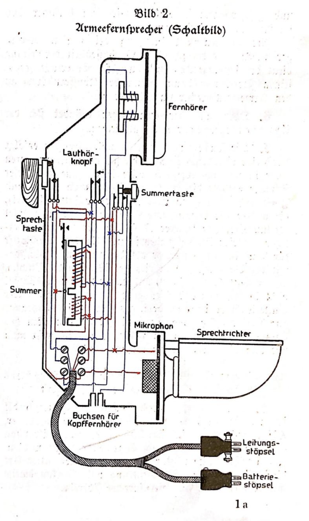
The microphone is located in the lower part of the army telephone; a foldable speaking horn is attached to the microphone housing to improve the sound waves when speaking. The talk button is located on the side of the handle of the army telephone, which is turned by about 90 degrees when the device is picked up, thereby closing the circuit required for the microphone. When the button is released, the power is interrupted again and the battery is not unnecessarily drained. Above the microphone is the white buzzer button, which activates the buzzer stored in the handle. When the battery is switched on and the circuit is closed, a loud tone is generated in the telephone receiver. The black loudspeaker button is used to improve communication in the event of loud background noise or poor quality of the line. However, it only serves its purpose when the headset is connected to the army telephone. The telephone receiver is located at the top of the army telephone. The army telephone is connected by a four-core cord, which splits into two two-core cords at its lower end. One of these cords contains the battery supply line and has a round plug (battery plug), the other for the line and earth has a flat plug (line plug); the latter is provided with clamps on the side. Both plugs have two pins each. The pin for the zinc is slightly thinner than the other pins so that the battery plug can be inserted correctly into the sockets on the battery and so that the line plug cannot be inserted into the battery sockets. The battery plug also has a screw attached as a marker. If you place the thumb of your right hand on this when inserting the plug, you will hit the other socket with the thicker pin.
The headset is set up in the same way as the telephone telephone; the coil ends are led in a two-core cord to a plug that has two pins and two terminals on the side; the pins fit into the sockets at the bottom of the army telephone and into the line sockets on the battery. The headset has an eyelet and hook for the head strap on the back.
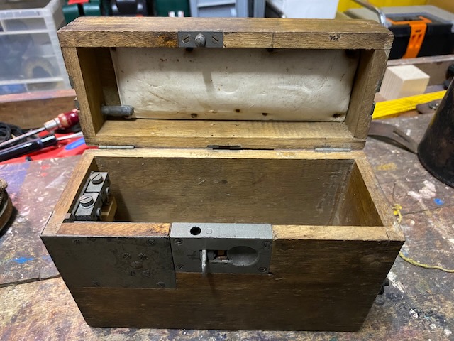
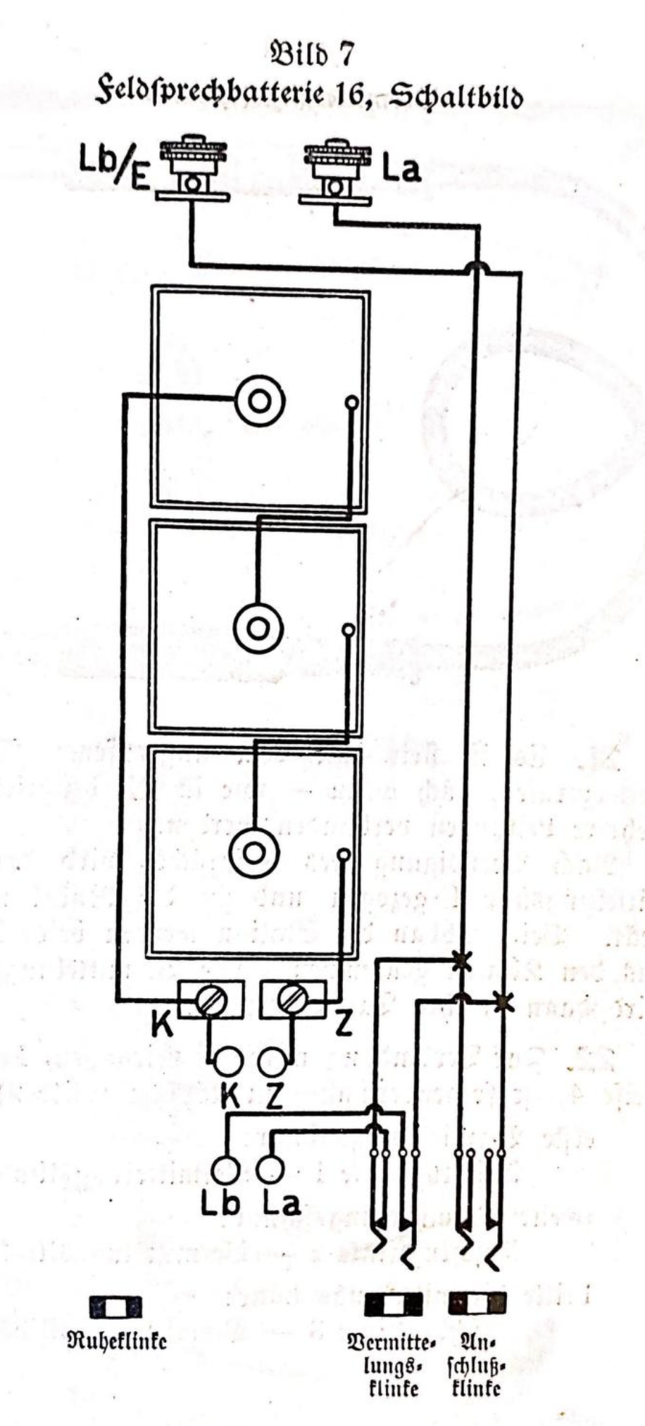
The field telephone battery 16 consists of a wooden box with a hinged, padded lid. On the narrow side of the battery box are the terminals for connecting the line - La - and the return line (earth) - Lb/E. A button screw is attached between the two terminals to prevent the cable drum attached to terminal La from touching terminal Lb/E. On the opposite end wall there are two jacks for switching on the right side wall and two pairs of sockets in the middle at the bottom. The line plug of the device is to be plugged into the lower one and the battery plug into the pair of sockets above it, according to the designations. The line terminals, the sockets La and Lb, and the jacks (connection and switching jack) are connected to each other. The rest jack is located in the lid on the same end. On the white writing board on top of the box you can write where the connected line leads. The spelling board is used to help you spell. The box contains three field elements connected in series inside. The series connection consists in the zinc pole wire of each element being screwed into the carbon pole screw of the next, so that at the end a carbon pole screw and a zinc pole wire remain free. The free carbon pole is connected by a piece of wire to the terminal marked K in the box; the zinc pole wire is placed on the terminal marked Z. To connect the elements together, the zinc pole wires must not be shortened, but must be connected with their ends to the following elements; the remaining excess wire is inserted between the elements.
"Zusatzkasten" (auxiliary box) description (translated and abridged) from "Ergänzungen zu der Vorschrift Das Fernsprechgerät der Feldartillerie." [3]:
The auxiliary box for the army telephone contains an AC ringer, an inductor, switchboard sockets, two foldable forks, a pair of sockets for the line plug, an inductor crank and the line terminals in a wooden box. The foldable forks are to be raised, they are used to hold the army telephone during pauses in the conversation. The left fork is movable and switches the line between the ringer and the army telephone. If the army telephone is on the forks, the left fork is pressed down and the ringer is connected to the line. If the army telephone is removed from the forks, the left fork moves upwards, switches off the ringer and connects the army telephone to the line. The army telephone is plugged into the pair of sockets on the left side with its line plug. (The battery plug goes into the battery sockets of a battery box). The La and Lb/E terminals are used to connect the line.
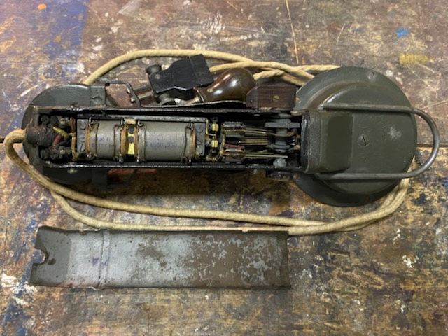
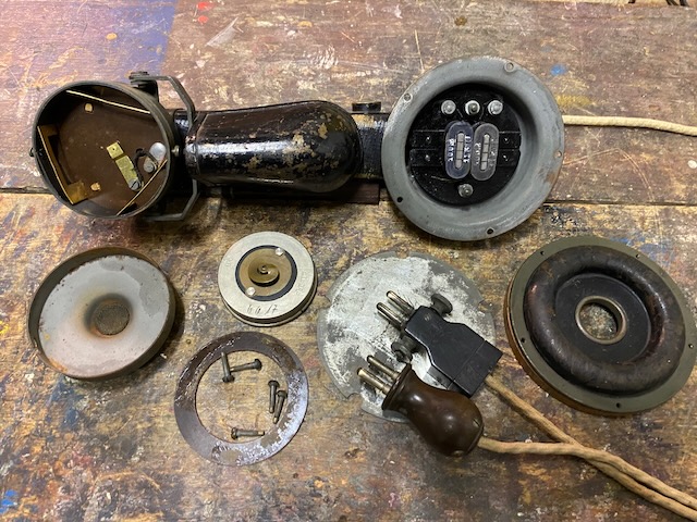
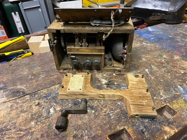
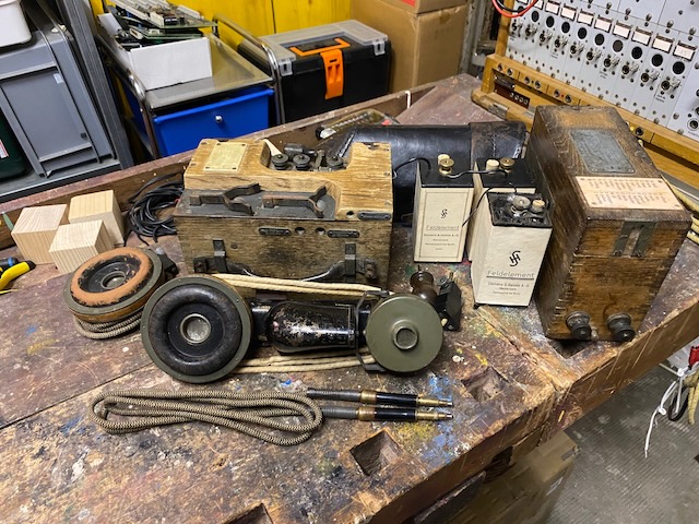
Disassembled.
The open back.
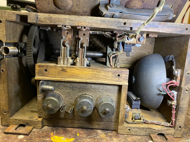
On the left the cord connections, then the coils, and to the right the switches mechanisms.
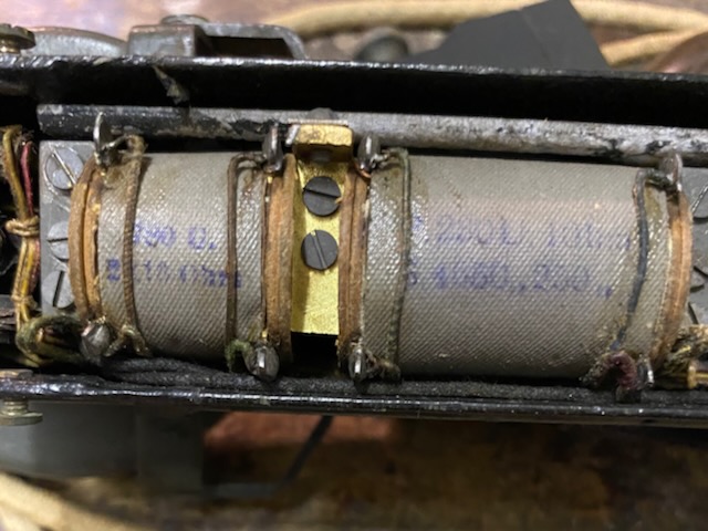
Left the buzzer coils (breakaway and degaussing coil) and right the voice coils (primary, secondary).
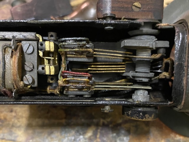
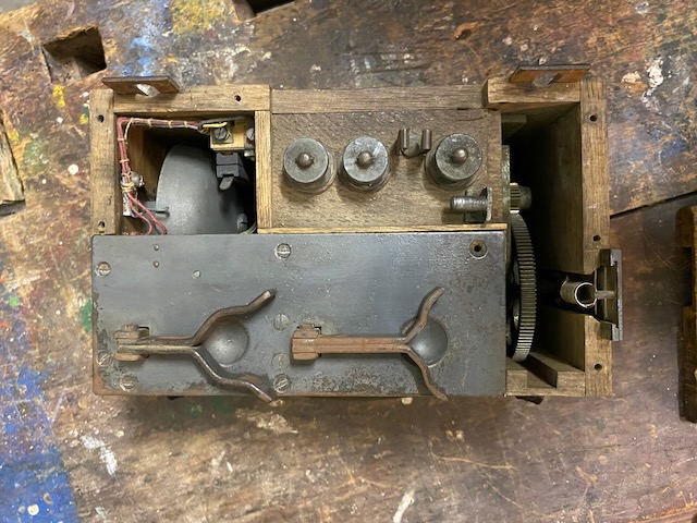
The switches mechanisms.
Top right the talk switch with the retaining spring.
Below the loudness button.
On the left in the middle behind the other switches is the buzzer switch.
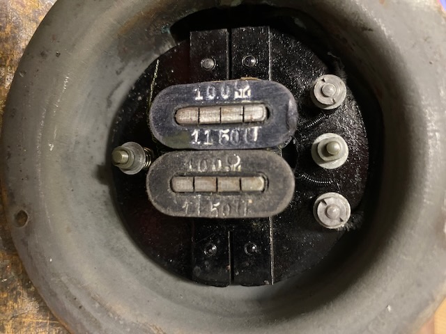
RX and TX side open.
Two 100Ohm coils make up the RX side.
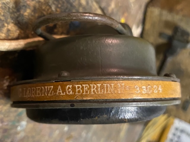
The TX capsule is made by C. Lorenz.
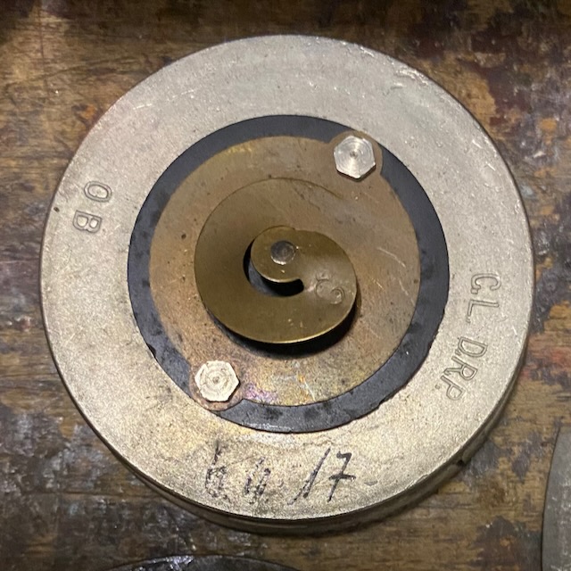
The manualinscription may be the mfg. date or the date when it was put into the device (day/month are not legible, 17 is assumed to be the year)
The whole device is made by C. Lorenz.
The wiring diagram of the "eiserner Armeefernsprecher" from [2].
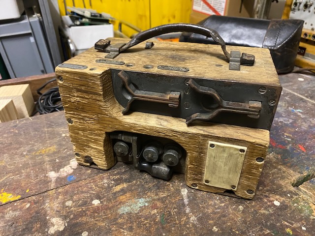
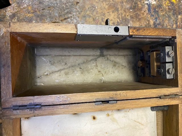
The open auxiliary box.
Inside the magneto and the ringer.
Also visible are the surge protectors and the switchboard sockets.
In the top left corner the hook switch mechanism is visible.
The hook switch plate mounted again.
The "Zusatzkasten" ready for transport.
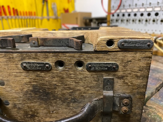
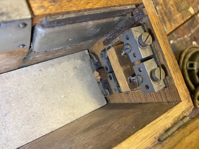
The switchboard sockets, to the left the "Anschlussklinke" (connection socket), to the right the "Vermittlungsklinke" (Switching socket) and top right the "Ruhe Klinke" (Resting socket).
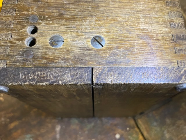
The "Zusatzkasten" was made by Gurlt which was also owned by C. Lorenz from 1915 onwards.
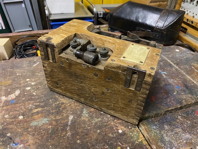
On the left the sockets for the "Armeefernsprecher" line plug.
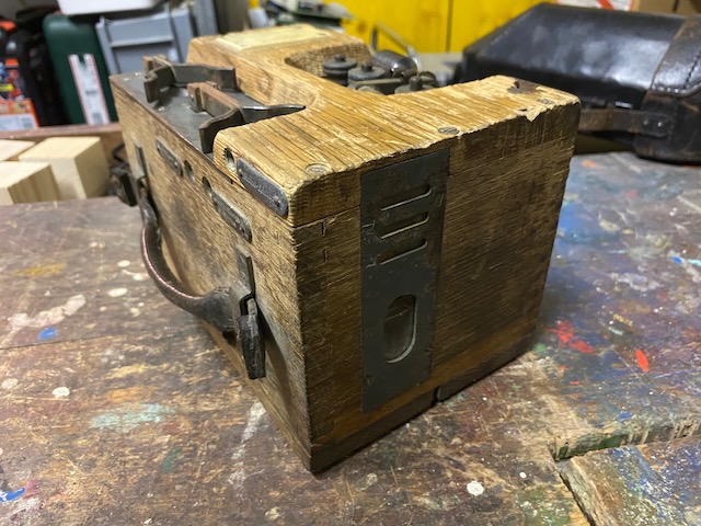
The Zusatzkasten top and back.
On the back latches to hang it up.
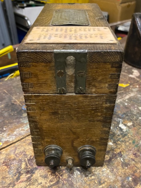
On top the line and earth binding posts, the storage for the magneto crank handle and a labe to be marked with line information.
The magneto handle hole is covered by a spring loaded moveable lid.
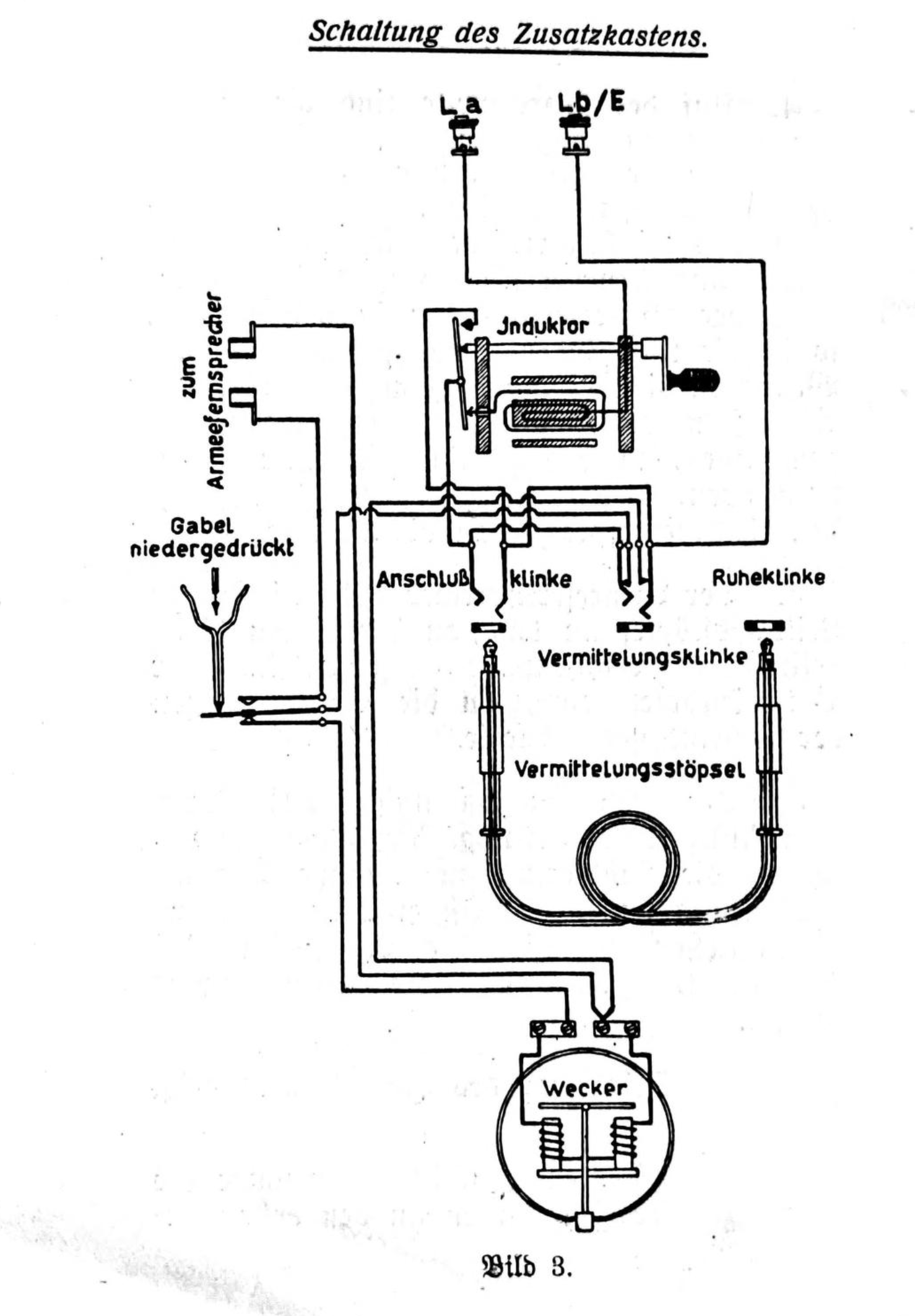
Wiring diagram of the "Zusatzkasten" from [3].
The battery box floor is covered in wax to protect the line wiring inlaid in the floor.
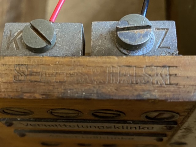
The battery connectors for Z (zinc) and K (carbon) which are wired to the battery sockets.
On the bottom the line sockets.
Inside of the lid is padded.
The battery box wiring diagram.
This battery box was made by Siemens & Halske.
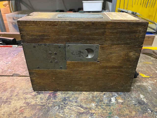
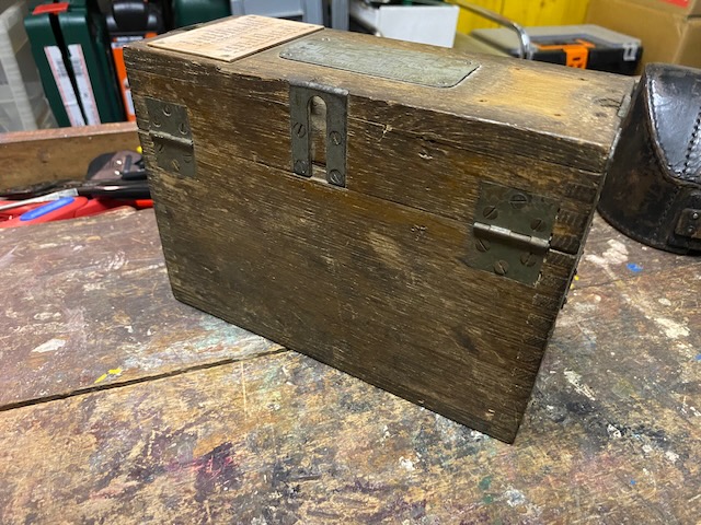
The closed box from the front.
On the top lid the diagram and a spelling table.
(The spelling table seems to be a replica, preserved too good compared to rest, and used nails look also too good)
The left marking label is missing.
The sockets from top to bottom:
The "Ruheklinke" (Resting socket), the Vermittlungsklinke (Switching socket), the "Anschlussklinke" (Connection socket).
The Z/K battery sockets for the "Armeefernsprecher" battery plug and at the bottom the Lb/La line sockets for the "Armeefernsprecher" line plug.
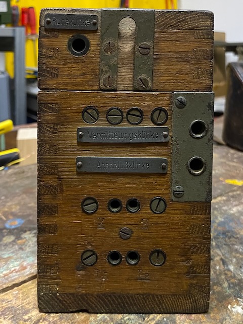
The line binding posts.
Back of the battery box.
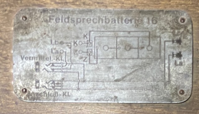
The wiring diagram of the "Feldsprechbatterie 16" from [2].
All neatly lined up, including an additional headset and 3 field elements (not original).
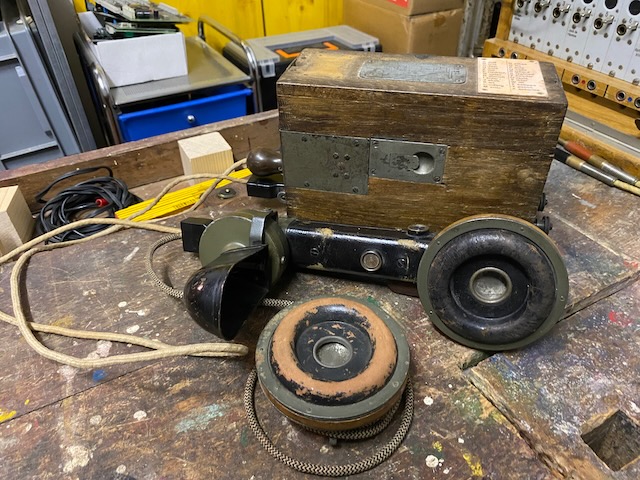
Ready to use for buzzer mode with the line and battery plug connected to the "Feldsprechbatterie 17" and the "Eiserner Kopffernhörer" (headset) connected to the "Armeefernsprecher" bottom sockets.
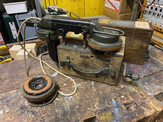
Ready to use for magneto mode.
The line plug is connected to the "Zusatzkasten".
Ready to store in the leather pouch.
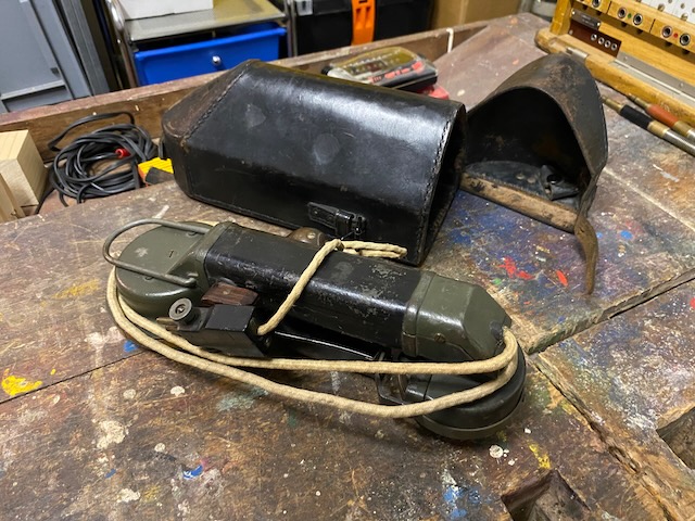
Stored.
Here the bottom sockets for the additional headset are visible.
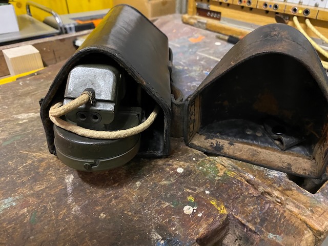
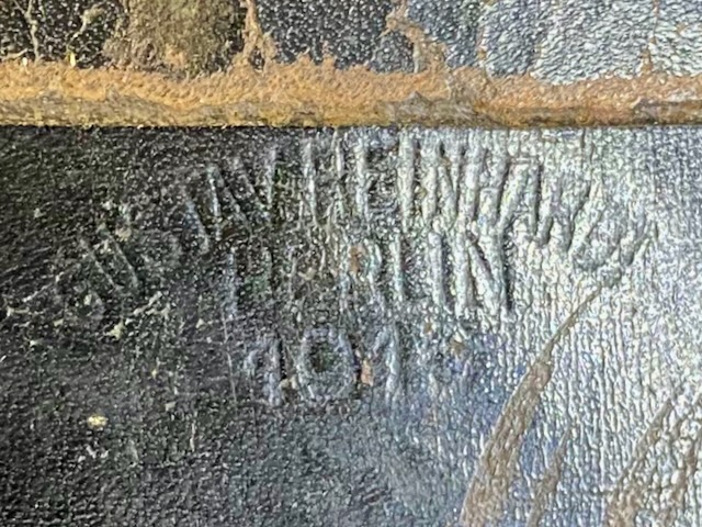
Leather pouch made by "Gustav Reinhardt Berlin", 1915.
Ready for transport.
![]()
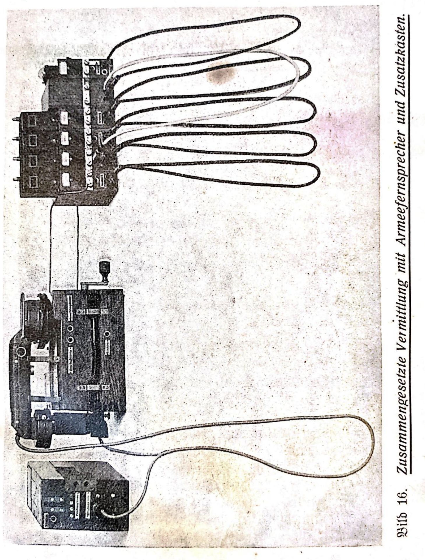
Example use as switchboard telephone and magneto with a couple of "Vermittlungskästchen" and a "Uebertragerkästchen" from [3].
Creative Commons Attribution-ShareAlike 4.0 International License