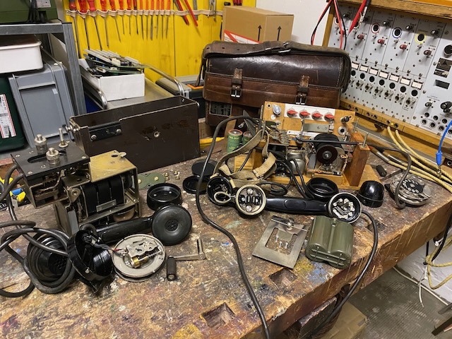
The Danish Fieldtelephone HSGT FTLF M/51L from the early 1950ies is quite remarkable as it is still built for single wire with earth return networks. Single wire lines with earth return were already quite "out of fashion" by the 1950ies as they were prone to interference and interception. It is the "recreation" of the Danish pre-WWI instrument M.1909/14 using "modern" components from Ericsson [1] [2] [3]. But in comparison to the 1909 model it supports connection to CB networks and even includes a dial. Also M.1909/14 used buzzer signalling (there was an external magneto/ringer unit available) whereas the HSGT FTLF M/51L has a built in magneto and ringer. The HSGT FTLF M/51 (without the L) is based on the Ericsson DPA 1152 [4] from the same line than the Swedish m/37. HSGT stands for "Hærens Signaltekniske Tjeneste" (Army Signal Technical Service) [5].
The HSGT FTLF M/51L is built into a sturdy leather bag. All components are mounted onto a wood chassis. All components except the switchboard are taken from the Ericsson DPA 1152. The Handset, headset and dial unit cables are fix connected (not pluggable).
The HSGT FTLF M/51 is built into a bakelite type case. All components are mounted onto a light alloy chassis. The Handset (there is no headset) and dial unit cables are fix connected (not pluggable).
Both instruments can be connected directly to LB or CB lines, there is no mode switch. In CB mode the microphone is still local battery powered, the PTT button on the handset has to be pressed to talk.
The HSGT FTLF M/51L single wire switchboard can be used to interconnect two or more (4) external lines with or without the local telephone connected. You could also connect eg. Line 1 and 2 external only and line 3 and 4 with the local phone attached. An external only connection can not be overheard, so to check status you would need to interrupt the connection shortly. The switchboard does not include any call indicators. A similar type of switchboard was also used by the Austria-Hungarian Mikrophonkassette M.07. How the respective networks would have been built is described in the "Telefonreglement for Fodfolket" from 1916 [3].
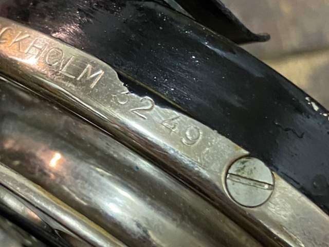
I did not yet find sources which indicate if these devices were built directly by Ericsson or by a danish subsidiary or licensed to another danish manufacturer, or which indicate the number of devices made. There is a serial number on the label (and on the handset stand inside), based on the highest number an internet search brought up is 3700 something (and on my devices handset stand it is 3288) and that the devices are not uncommon to be found on the typical marketplaces I assume the number made to have been in the 5000 range.
Disassembled.

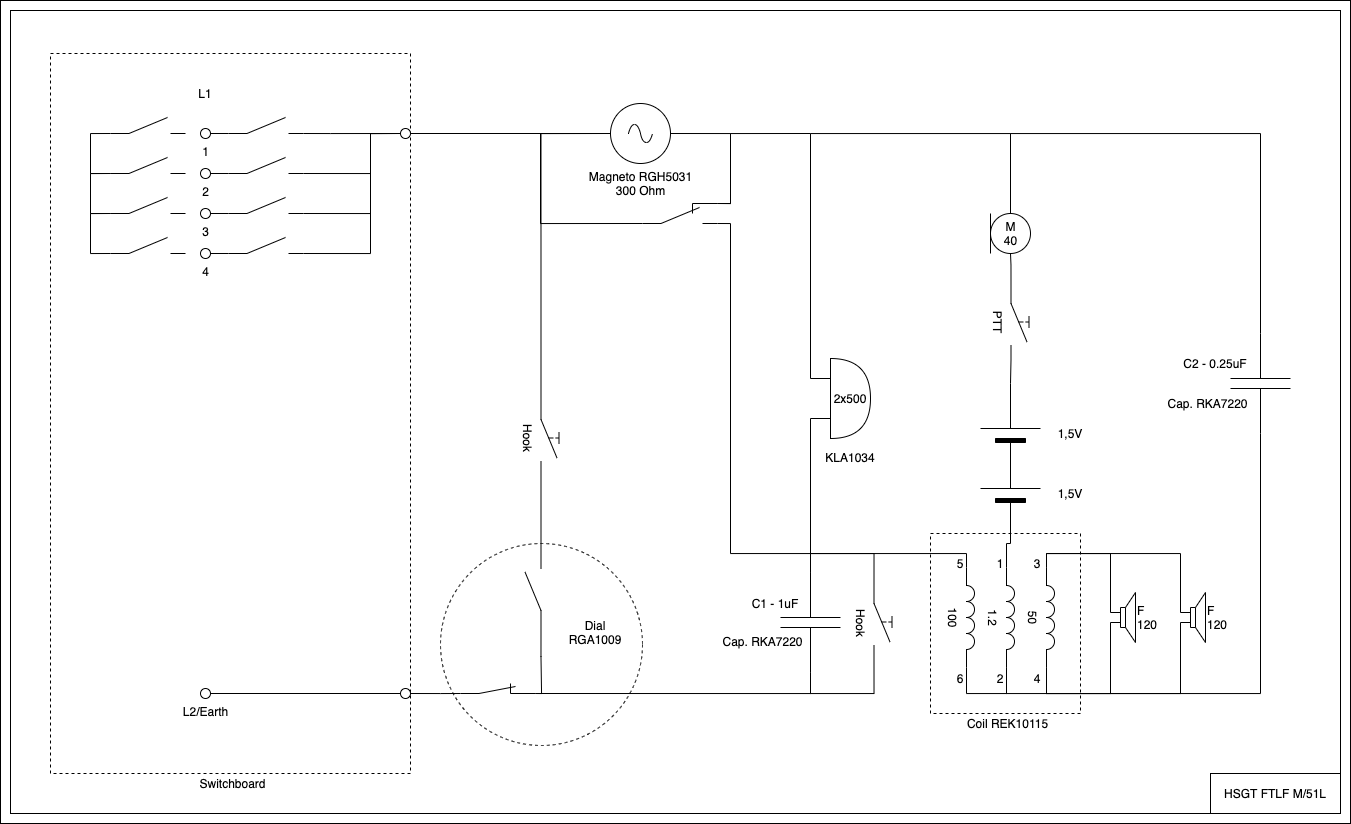
Diagram (self made, click it for bigger version).
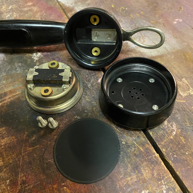
The bakelite handset with removed caps.
A typical Ericsson style handset, with a lug to hang it somewhere.
The TX module RLA 1604 has a date-code from 1949.

RX side base/holder of receiver coil/magnet removed..
Headset receiver open.
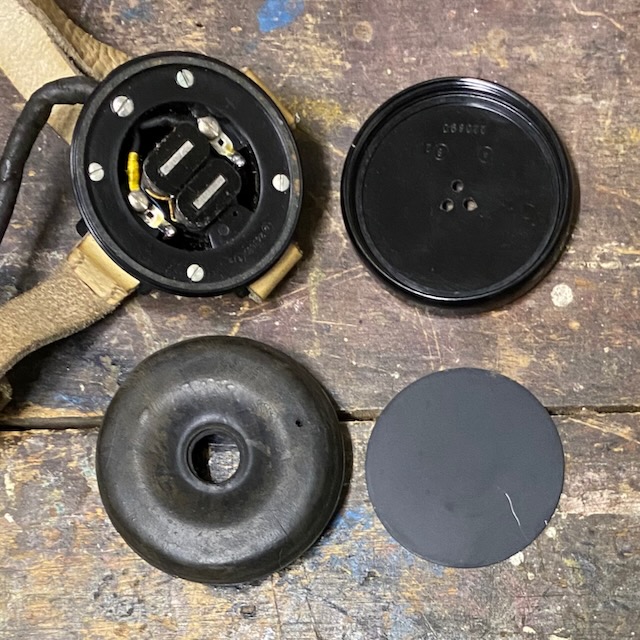
Ericsson mark on headset back.
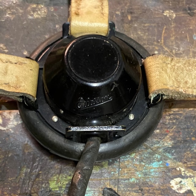
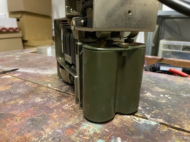
Battery holder.

Wood chassis front with switchboard on top removed.
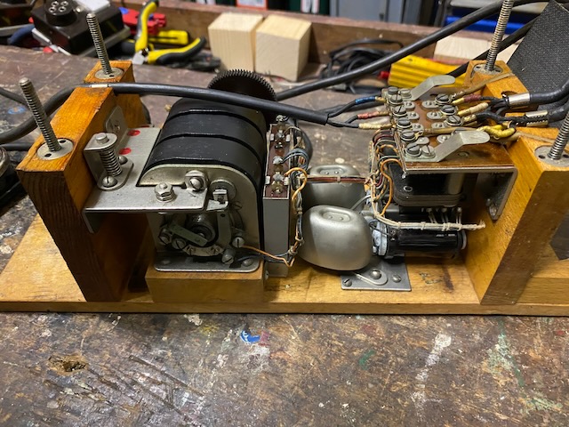
The coil is mounted below the connector board.
Below that the ringer and. to the right of the ringer the magneto.
To the right of the magneto the "hook switch" assembly.

Wood chassis back.
On the left of the magneto the spring loaded hook switch mechanism.
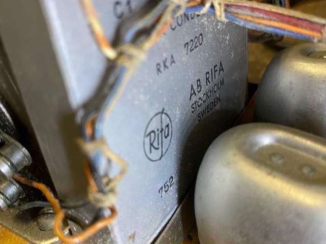
The capacitor is made by RIFA (Ericsson owned) in 1952.
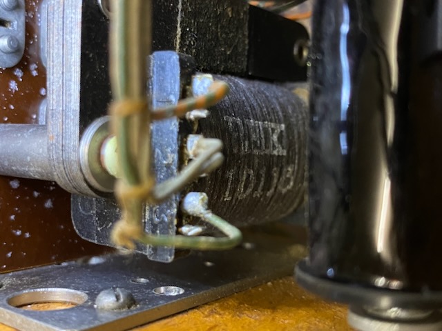
Coil REK 10115.
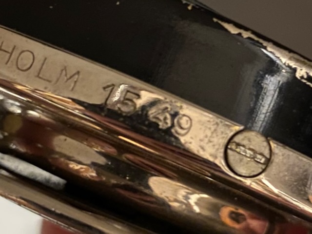
Datecode on dial, 1949.
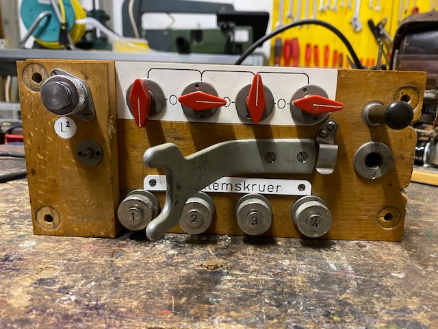
Top of switchboard.
On L2 the earth/common wire would connect in case of use with single wire switchboard function.
On 1..4 the respective single wire lines get connected.
A red switch in "down" position connects that line to the phone, in the up position it connects it to the switchbar, in vertical connection (to 0) the line is disconnected.
On the handset stand the serial/inventory number is 3288 (not the same than on the case label, most probably mixed up sometime womewhere).
The black button/lever to the right is the hook switch activator.
The hole below the switch activator and the small latch to the left of it are to store the magneto lever.
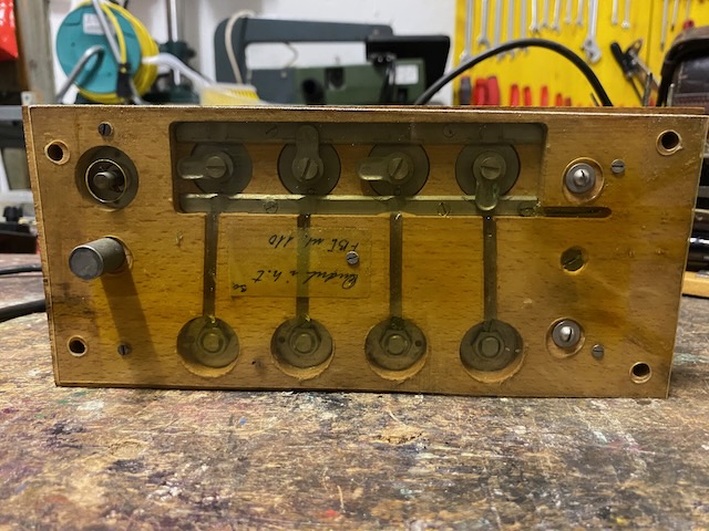
Bottom of switchboard.
A clear plastic sheet is mounted to protect against dirt on the switchbars.
There is a note attached i cannot read, perhaps a repair or modification indication?
The top switchbar connects between lines, the bottom switchbar is connected to the phone.
The two domed screws on the right connect the L2 and the bottom switchbar electrically to the phone circuits.
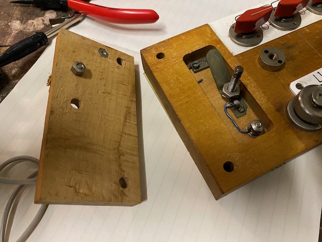
On top of the switchboard the electrical connections from the switchbar and the L2 connector are wired to the screws which make electrical connection to the phone circuit.
Neatly arranged parts.
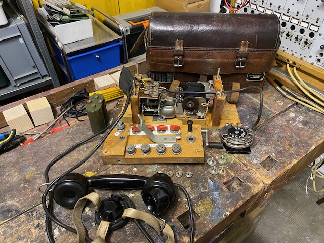
Battery holder mounted.
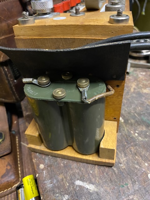
Assembled and ready to use in CB/Aut. mode.
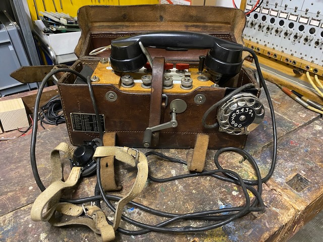
In LB mode the instrument can be used with closed lid.
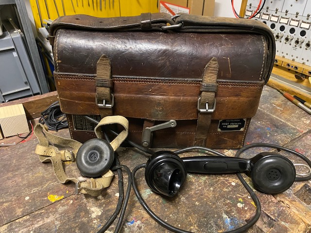
Handset, headset, dial and magneto lever stored.
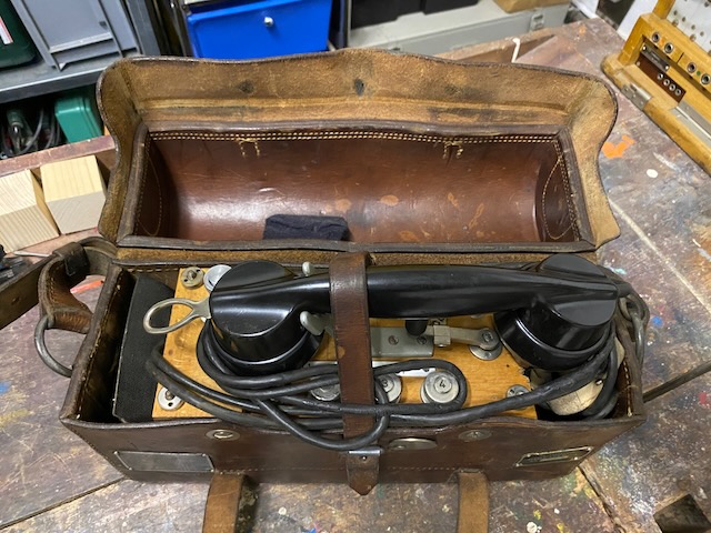
Ready for trasnport.
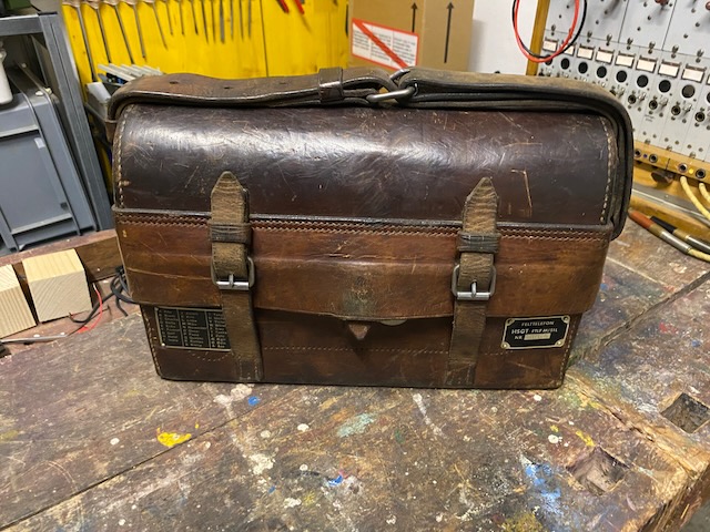
From the back.

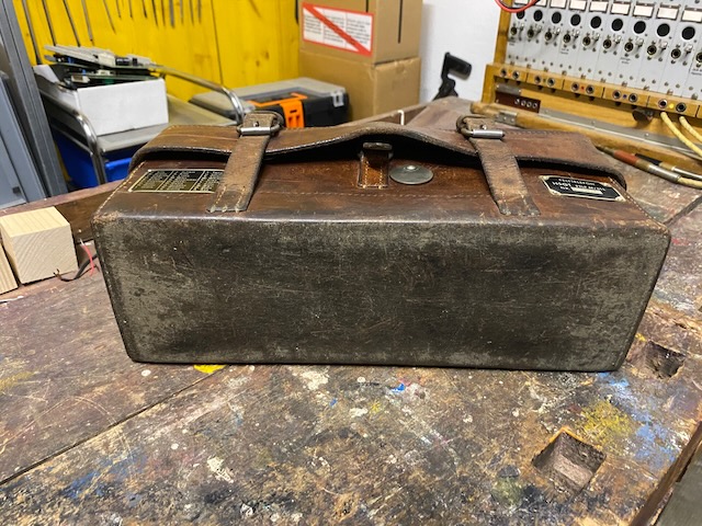
And from the bottom.
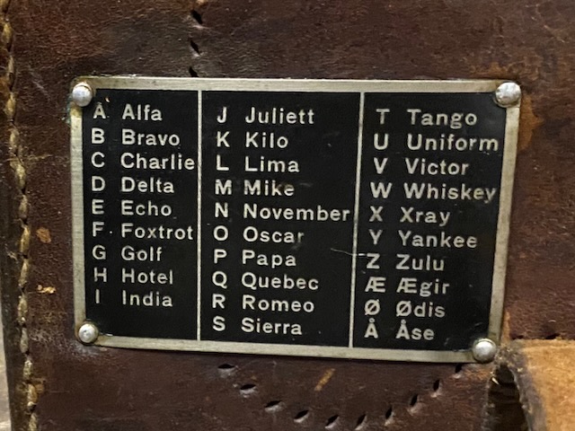
The spelling table label, NATO spelling table extended with three danish special characters.
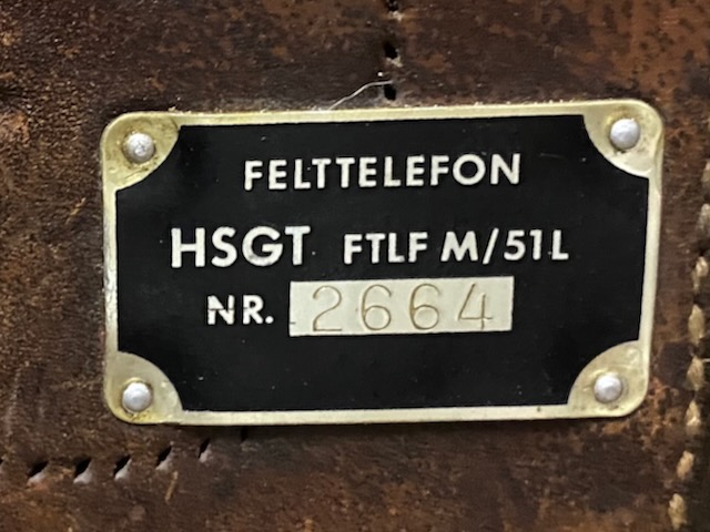
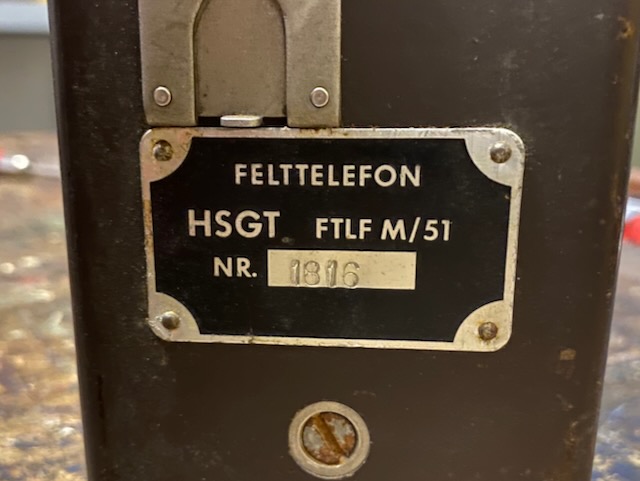
The type label with a serial/inventory number.
The M/51 parts neatly arranged.
The chassis top is marked with a serial/inventory number.
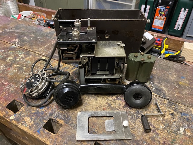
The chassis from the front.
Coil, capacitor, magneto and below the ringer.
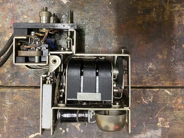
The chassis from the back.
On top the hook-switch assembly.
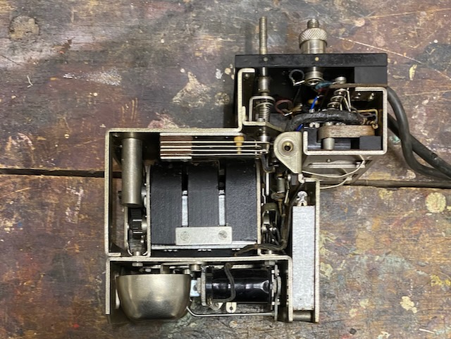
From the bottom, ringer with nice slim bells.
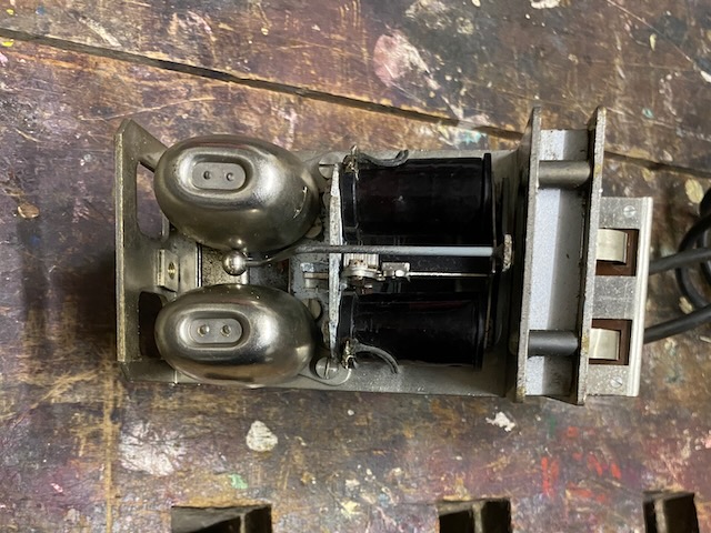
The dial with removed back.

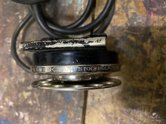
Made by Ericsson Stockholm.
Date code of 1949.
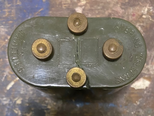
Top of the battery holder indicating how to put in the cells.
"Anbring celleren Saaledes" = "Place the cells like this"
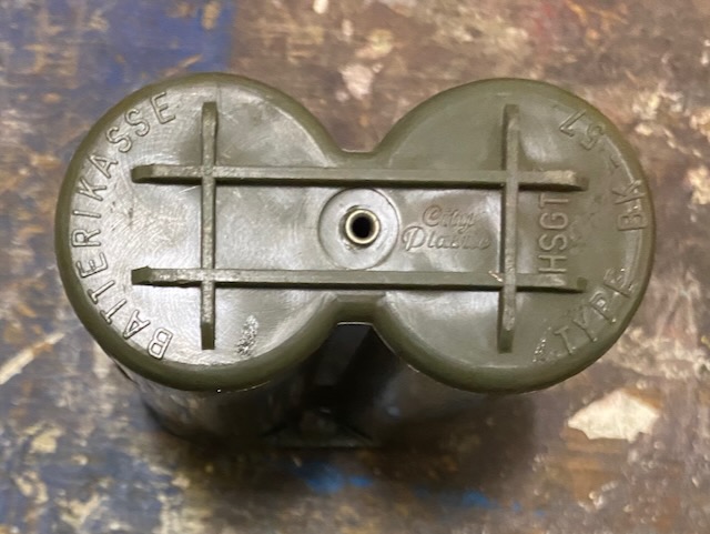
Bottom of battery holder.
Made by "City plastic".
"Type BK-57" may indicate that before 1957 another type of battery was in use (most probably the 3V B3a battery, Ericsson product IDs BKA1101/2101).
Showing where the battery holder sits when mounted.
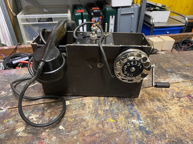
Ready for CB/Aut. use.
The type label with a serial/inventory number.
Handset, dial and magneto lever stored.
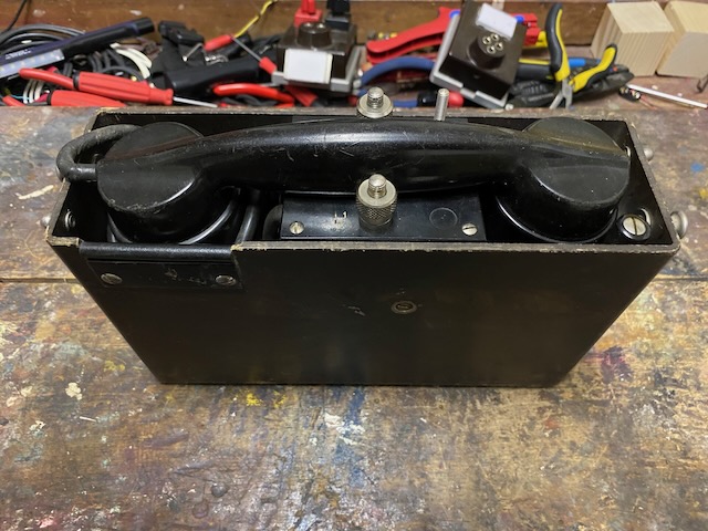
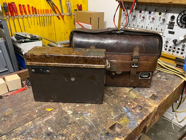
M/51 and M/51L.
The lid of the M/51 is unfortunately not the original, it is from a Swedish TFNAPP MT.
Creative Commons Attribution-ShareAlike 4.0 International License