This is the predecessor to F. Mk. II. The differences between F. Mk. II and I are: bakelite instead of cast alloy metal case, induction coils (no. 21) replacing the buzzer (T. Mk. I), generator type "C" instead of "B" [2]. F. Mk. I seems to have been developed in the mid 1930ies [3] and replaced by F. Mk. II circa 1940 onwards.
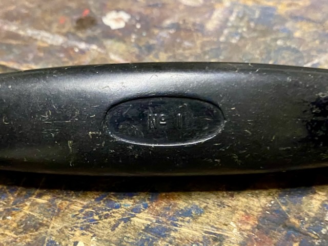
The here presented is made by Plessey in 1939 and of type F. Mk. I*. The only difference between Mk. I and I* seems to be the handset, No. 1 for Mk. I and No. 3 for Mk. I*. Though the here presented has a Tele Hand No. 1. I currently don't own a handset No. 3 and have yet to finde documentation as to the differences between No. 1 and No. 3.
General description (abridged) from [1]:
Purpose and facilities: The Telephone Set, F, Mk. I is a portable instrument for army communication. It is not normally used forward of divisional headquarters. It provides the following facilities : I. Calls by buzzer. II. Calls by magneto generator. III. Responds by bell to magneto generator calling. IV. Responds by aural indication to buzzer calling. V. Speech communication. The telephone will give visual indication of a call to Switchboards U.C. by magneto generator and buzzer, and to Switchboards F and F by magneto generator. Visual indication of a call to Switchboards Central Battery Signalling (C.B.S.) is given by removal of the handset from the cradle. The Telephone Set, F. Mk. I*. is similar to the Telephone Set, F. Mk. I. except for small constructional differences. Details given in this pamphlet of the Telephone Set, F. Mk. I, apply to the Telephone Set, F. Mk. I*. except where otherwise stated.
Range of working: Reliable speech cannot be obtained through more than 14 to 16 miles of D8 twisted cable or 8 to 10 miles of D3 twisted cable. This corresponds to an attenuation at 800c/s of approximately 30 to 40 db. These distances refer to cable in good condition having a minimum number of well-made and well-insulated joints. The use of deteriorated cable, or cable with indifferent joints, may easily reduce these ranges by as much as 50 per cent. Wet cable and cable laid on the ground, even in good condition, will always give shorter ranges than dry cable or cable supported off the ground. A single line and earth circuit may give better or worse ranges than a twin line. In general the earth circuit tends to give better and better results relative to the twin line as the distance increases. The effect of bad earths, such as small earth pins in dry sandy soil, may be of the same order as an increase of 10 or 15 miles in the length of the line.
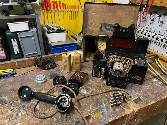
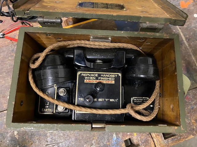
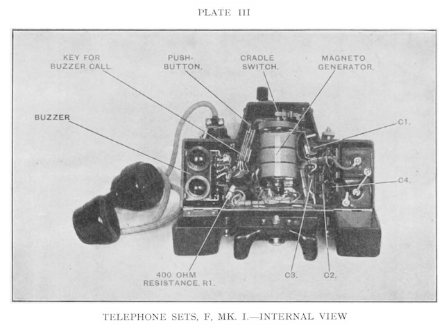
Constructional details: The Telephone Set, F. Mk. I. is housed in a metal case which in turn slides into a wooden carrying case provided with a sling. A spring stop, which holds the unit in position in the carrying case, is pressed down for the unit to be drawn forward into the operating position. A second stop prevents the unit from sliding completely out of the case. When in the operating position, the outer case gives reasonable protection to the instrument when working in bad weather. The batteries and the buzzer may be removed from the instrument by first withdrawing it completely from its carrying case, removing the handset from the cradle and unscrewing the two captive screws beside each bell gong. When the lid of the instrument is lifted the batteries will be found at the left-hand side. The lid of the battery compartment, which contains two " S " or " X " type dry cells, is lined with paxolin sheet in order to prevent any possibility of short-circuits. The two bell gongs are located on top of the instrument, the hammer of the bell mechanism projecting through an opening in the lid between the gongs. The buzzer, the magneto generator with its associated line connecting switch and gearing, the bell mechanism proper, the condensers, switches, etc., are all contained inside the metal case. The buzzer slides downwards into a compartment on the right-hand side, the connections being made on the left-hand side of the buzzer by contact springs. The adjustment of the buzzer can only be carried out with the lid of the instrument open.
Disassembled.
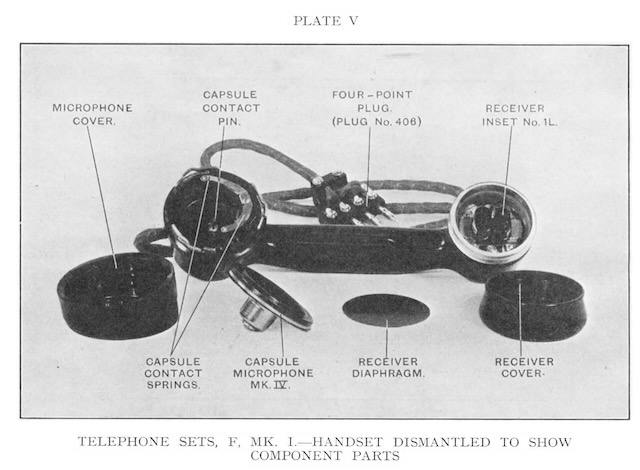
Tele Hand No. 1.
Disassembled.
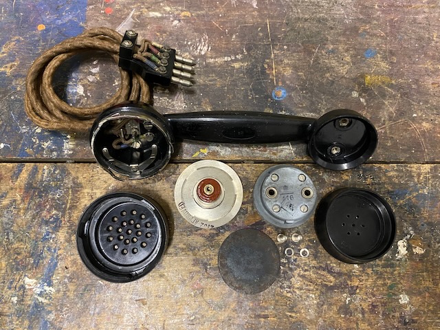
No. 1, according to [1] a Tele Hand No. 3 was used with F. Mk. I*.
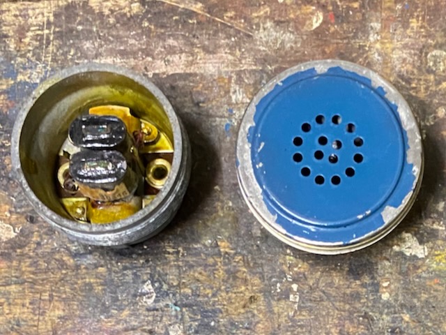
Back of receiver inset No. 1L and microphone capsule.
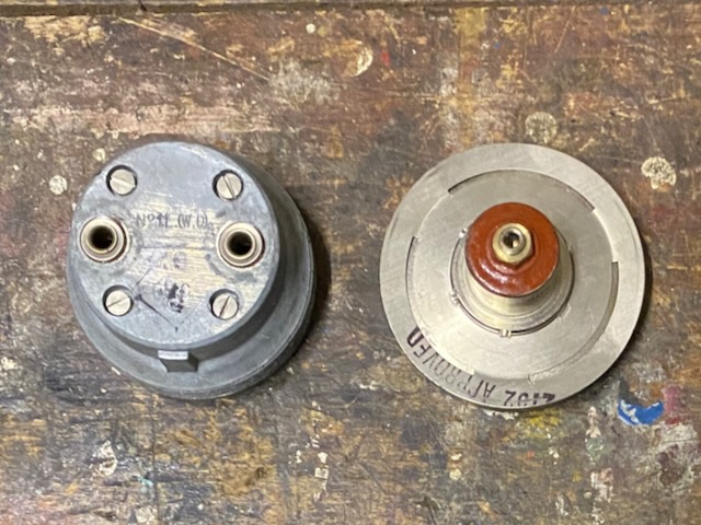
Frontof receiver inset No. 1L and microphone capsule.
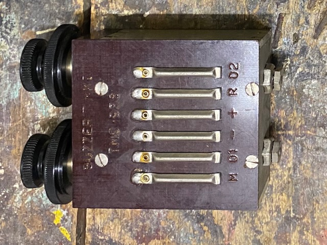
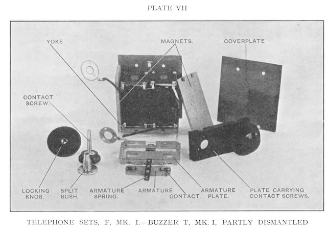
Buzzer T. Mk. I.
Made by T.M.C., 1938.
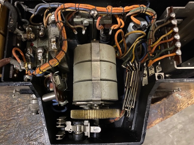
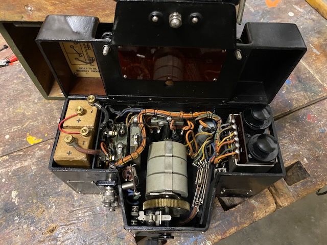
From left to right: Capacitors, ringer and magneto in front of it, holding coil, buzzer compartment.
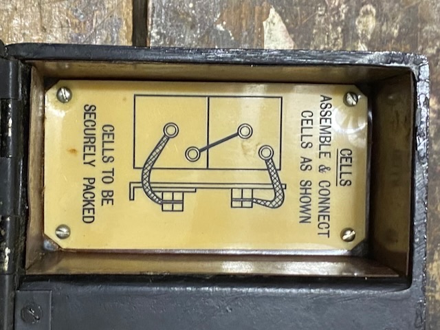
Battery guide inside lid.
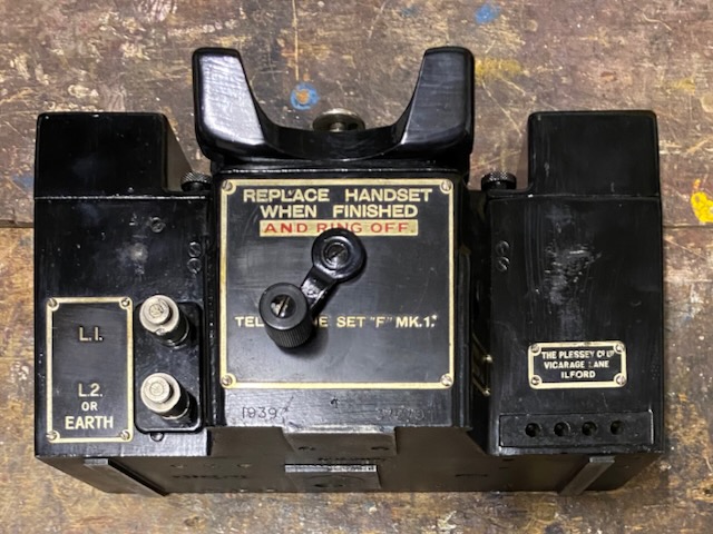
Front.
Below magneto handle the year of make (1939), broad arrow (/|\) and serial number are marked.
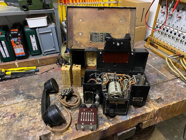
Neatly arranged to assemble.
Batteries and buzzer mounted.
Empty box.
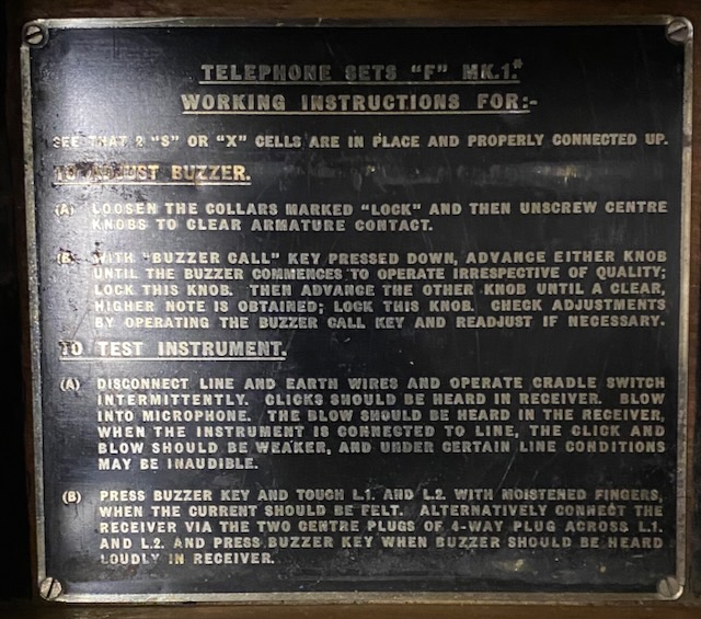
User guide in the back.
![]()
User guide.
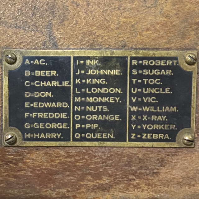
Spelling table (spelling table type which was used 1938-1942).
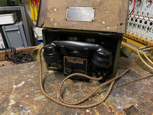
Ready to use.
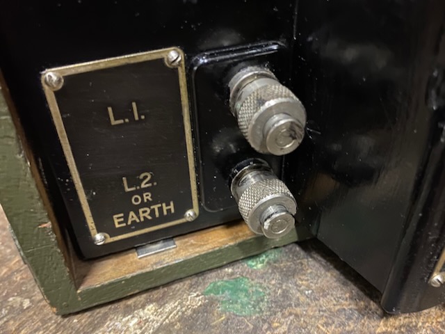
Binding posts.
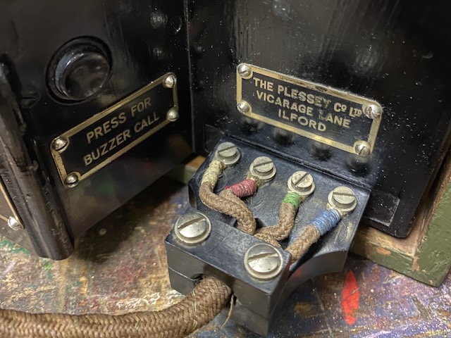
Buzzer button and handset plug.
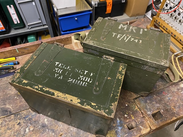
Ready to store.
Ready to transport.
![]()
F. Mk. II in front of F. Mk. I*.
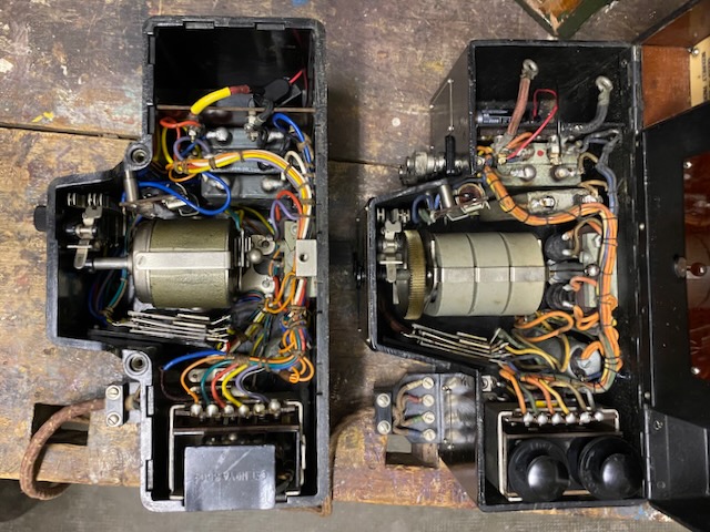
Left F. Mk. II, right F. Mk. I*.
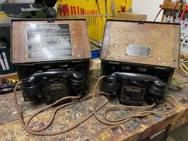
Left F. Mk. II, right F. Mk. I*.
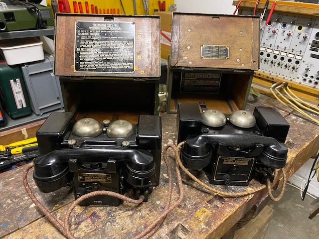
Left F. Mk. II with lid removed, right F. Mk. I*. with lid open.
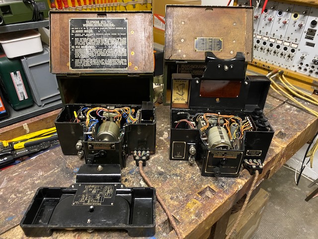
Left F. Mk. II, right F. Mk. I*.
Note the different magnetos, "C" on Mk. II. and "B" on Mk. I*.
F.Mk.II. has a coil (No. 21) inserted replacing the buzzer.
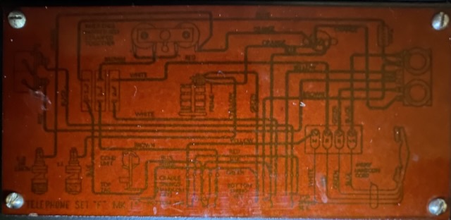
F.Mk.I* diagram (mounted inside lid, not very readable).
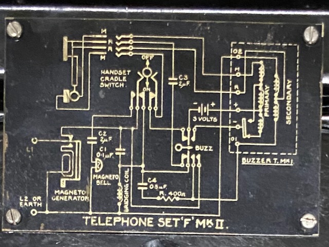
F.Mk.II diagram (mounted inside lid).
F. Mk. I, I* and II diagram from [2].
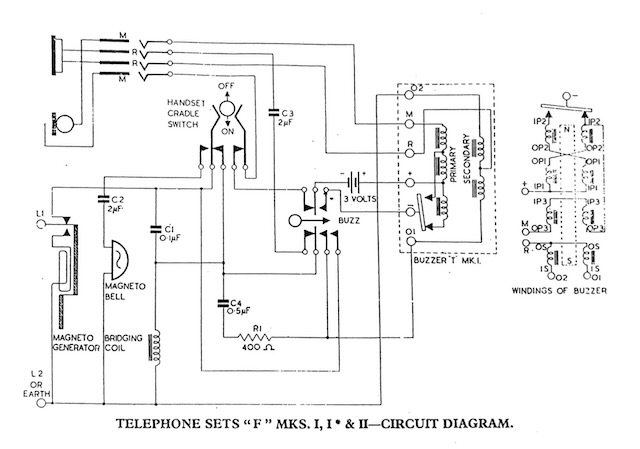
F. Mk. I diagram from [1].

Dismantled handset from [1].
Open set from [1].
Dismantled buzzer from [1].
Creative Commons Attribution-ShareAlike 4.0 International License