Find more details on U.S. field telephone history on the U.S. Signal Corps Field Telephones Timeline.
The Service Buzzer Model 1914 replaced the earlier field buzzer, the cavalry buzzer and the field artillery telephone [1]. Later it got the electrical engineering equipment group number EE-63, it is still mentioned in the Basic Field Manual of 1931 [2].
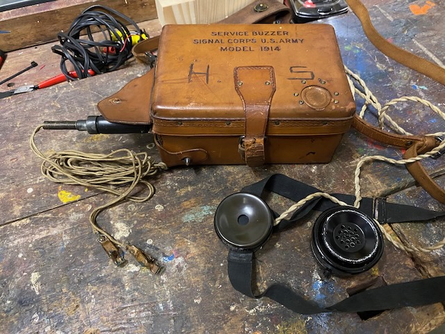
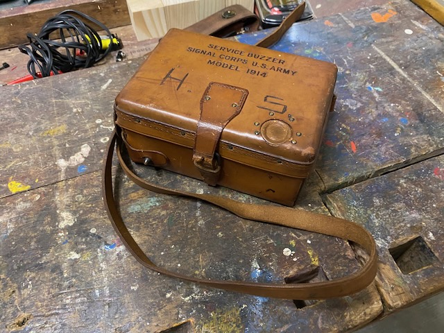
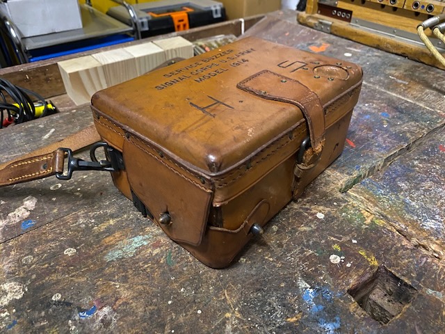
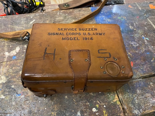
The instrument is contained in an aluminum case fitted with a hinged cover, both of which are covered externally with a russet-coloured, smooth-finish leather which is neatly sewed and riveted in place. The overall outside dimensions of the case are approximately 33 by 51 by 71 inches. The two units of Tungsten type A battery are contained in a chamber located in the bottom and are accessible without opening main cover, there being an additional small hinged cover in one end of case which is fastened securely, when closed, by a substantial spring clip, and by a flap of leather.
The instrument may be operated with both covers closed, which is highly advantageous in inclement weather. To accomplish this there is a suitable opening for leading out the cords to receiver and transmitter, and in main cover, directly over the sending key, is a round aperture which is made moisture-proof by means of a covering of extremely flexible pigskin. The sending key can be readily operated through this flexible pigskin.
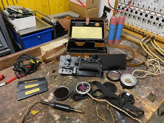
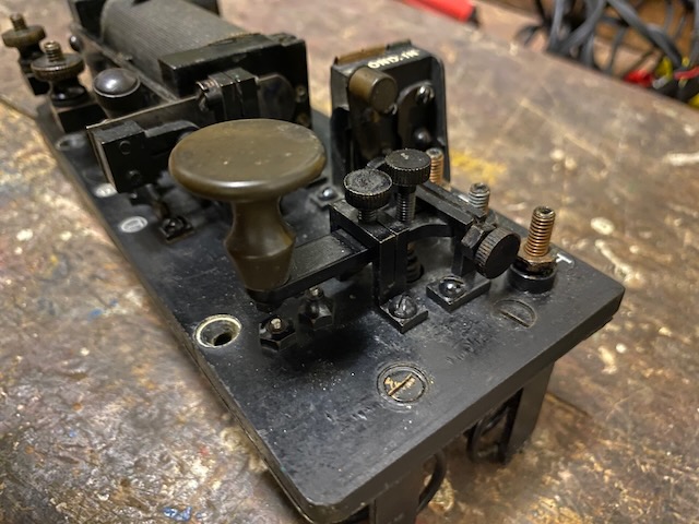
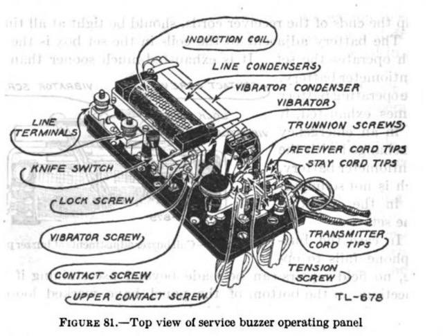
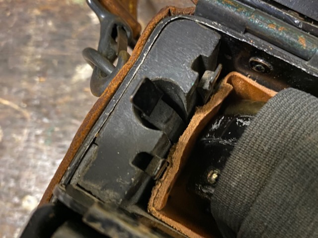
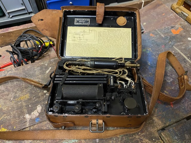
The sending key, induction coil, condensers, plug jack, transfer switch, vibrator, and binding posts for transmitter and receiver cords are mounted upon a common base of hard rubber. Wiring to the component parts is routed in the underside of this base, which is mounted in the front of the case above the battery chamber previously mentioned. In the rear of the instrument is a compartment of leather for containing the transmitter, receiver, and cord for connect ing them. At one end of this chamber, neatly mounted on a hard rubber strip, is a socket wrench for adjusting the nuts which secure the transmitter and receiver terminals, also two screw drivers — one large and one small — which are so constructed that the shanks may be inserted in the end of socket wrench, thereby using socket wrench as a handle.
Invariably there is furnished with this instrument a two-conductor cord, approximately 5 feet long, one end of which is equipped with a substantial plug similar to those used in connection with telephone switchboards. At other end one of the conductors is equipped with a Williams test clamp for connection to line, the other conductor being equipped with a Signal Corps type D ground rod. The Williams test clamp is so constructed that to attach to line, it is merely necessary to compress the two principal parts, releasing them when line has been inserted in space provided. One side of this clamp is equipped with an 11-point stud securely threaded to test clamp. These points make excellent contact on line, regardless of whether the line be insulated or not. By this means a quick connection can be made to buzzer wire or field wire which is insulated, and when the clamp is removed the abrasion to insulation is negligible. There is an opening in the case of buzzer through which the plug is inserted when connection is desired, and when plug is so inserted, it makes a positive connection by means of a substantial jack mounted on the base as previously indicated.
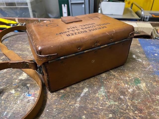
The case has an adjustable carrying strap, one end of which is equipped with a snap connection, the other end being sewed to hinged fitting on case. The instrument, including carrying strap, type ground rod, Williams test clamp, plug and 5-foot cord, weighs approximately 5 pounds, and full directions for operation, together with a circuit diagram, are attached to the inside of main cover.
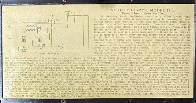
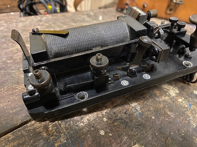
(a) Operator should familiarise himself with buzzer circuit. This Instrument should be tested at such times as may be necessary to insure efficient service when used In the field and any troubles which cannot be remedied reported to Company Commander. Instrument base is lifted by removing screws inside circles. To use as a buzzer, switch lever should be to the left, or on "B." and to use as a telephone, to the right, or on "T." The Instrument may be used as a buzzer when switch is thrown to the right, but will be found to be more efficient for this purpose when thrown to the left.
(b) To test battery: Short-circuit the Jack with instrument tool by inserting between barrel and spring of Jack. Pressing the spring in the transmitter should be distinctly heard in the receiver and condition of talking circuit can be determined by blowing briskly in the instrument which should be distinctly audible in the receiver.
(c) To test buzzer: Press the key and buzzer should work immediately on open circuit; then insert plug in jack with line connected, and, if the line is normal, should work satisfactorily without any appreciable change in note. The buzzer should give a clear, continuous high note and respond quickly to the use of the key. If the buzzer is heard in sending Instrument, the telegraph key is not breaking receiver contact underneath.
(d) To adjust buzzer: Buzzer is adjusted by means of two screws. The screw nearest spring seat is to regulate the air gap which should be attended to first and which determines the rate of vibration. The contact screw in post should be set in a position of greatest efficiency and locked by screw through split portion of post. By careful adjustments the buzzer will give very satisfactory results. Excessive sparking between the contact and vibrator spring indicates that the bridging condenser furthest from induction coil is open. If spring pulls up with sharp click when key is closed and no buzzing results, it is probable the condenser is short-circuited. Either condition can be determined by removing the condenser. To Set close adjustment on key, turn upper contact screw down until the desired adjustment is obtained, then bend up the projecting piece under the lever until the auxiliary contact is just open when the lever is up.
(e) To test receiver: If receiver circuit Is thought to be dead it can be tested by disconnecting the cord terminal on (R) post and touching it on the post marked (T), and if it is in good condition a loud click in the receiver will result. If no click is heard it is an indication that the receiver or cord is defective.
(f) To test line: If after plug is inserted in jack the buzzer operates very faintly it is an indication of a short-circuit near the instrument in the plug, cord or connector. If ground circuit is used this may result from a ground on the line near the instrument. This can probably be determined by listening in the receiver, and if circuit is grounded receiver will be found very noisy. Care should be taken to provide a good ground in moist earth.
(g) If batteries appear to be at fault, the battery door should be opened and the tubes withdrawn and examined to ascertain If the outside shells of the batteries are in contact. Also to see if contact springs at bottom are pressing firmly against the cell couples. The top of cells should protrude almost to a level of the instrument case when battery door is opened to insure efficient compression to make good contact. Batteries can be tested by use of the receiver in the usual manner.
(h) Most troubles in this instrument will be found to be with the battery contacts, broken screws and telegraph key.
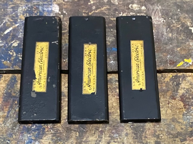
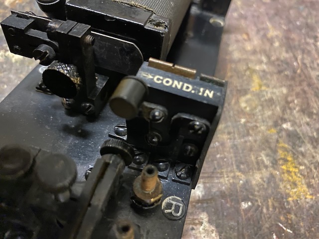
Field replaceable capacitors. Three identical capacitors, one for the buzzer spark suppression and two for capacitive coupling onto a telegraph line. In case the spark suppression capacitor is defective one of the other two can be used as replacement.
Disassembled.
Ready to use.
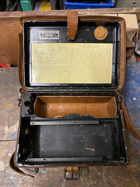
Electrical diagram (here called "theoretical diagram") and instructions mounted inside top lid.
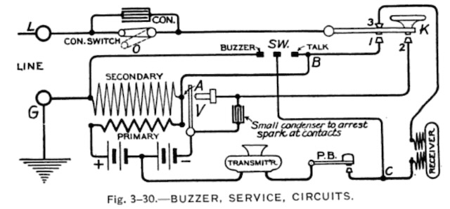
Functional diagram from [1].
Three identical field replaceable capacitors.
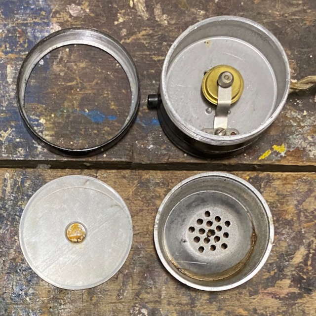
Microphone enclosure open.
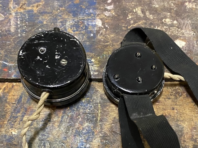
Microphone back open.
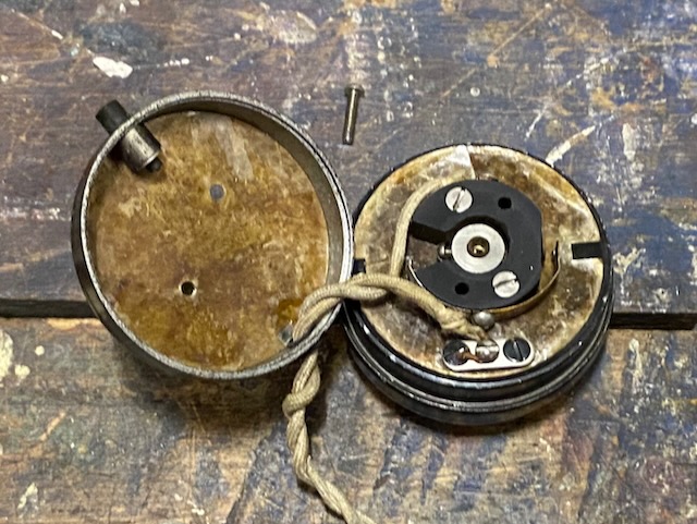
Receiver open.
Microphone and Headset front.
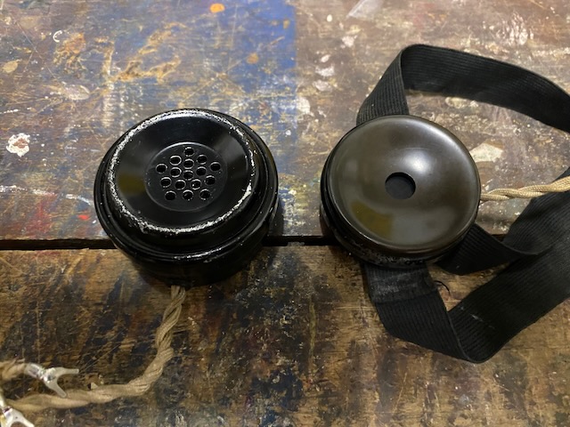
Microphone and Headset back (a screw is missing on the microphone).
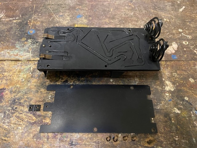
The electrical connections are inlaid into the main board bottom.
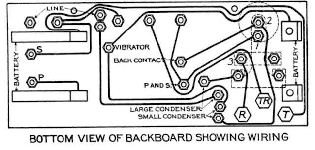
Wiring diagram from [1].
Buzzer key.
Top view from [2].
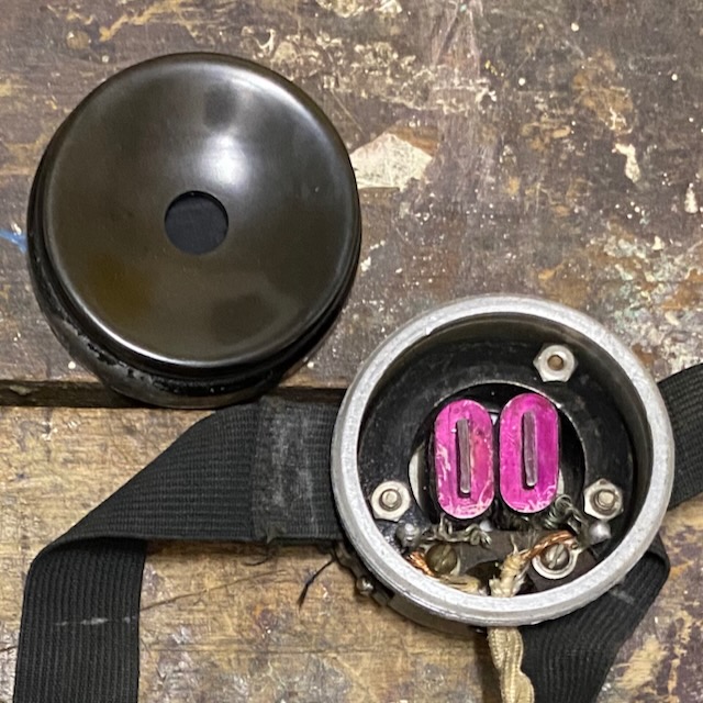
The plug, line binding posts and the "B" - "T" switch/lever.
The capacitor short circuit lever.
When moved right short circuit is open = capacitor in line.
Empty box.
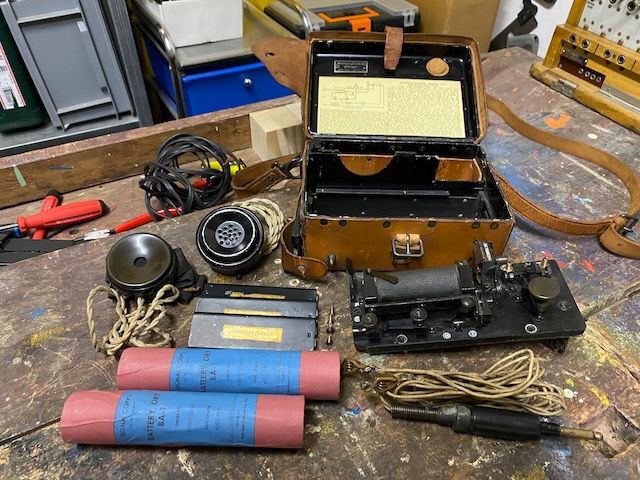
All parts ready to mount.
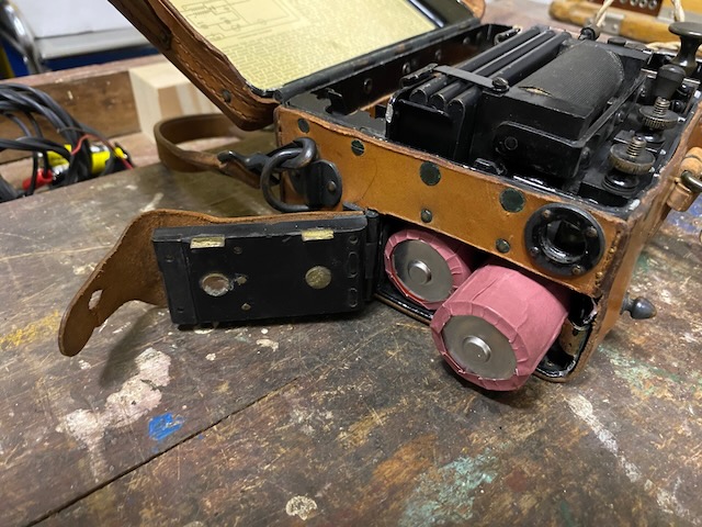
Battery door open.
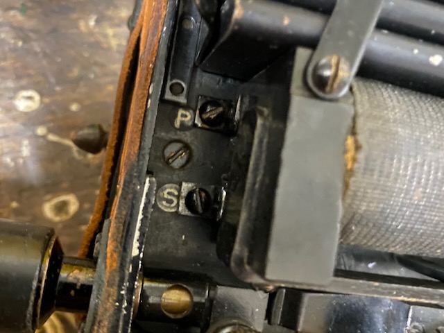
"P"rimary and "S"econdary marking on coil connection.
These springs would hold the tools which are missing (Wrench and two screwdriver bits).
Mounted and all stored.
Ready for transport.
Line plug lid closed.
Top view.
Back view.
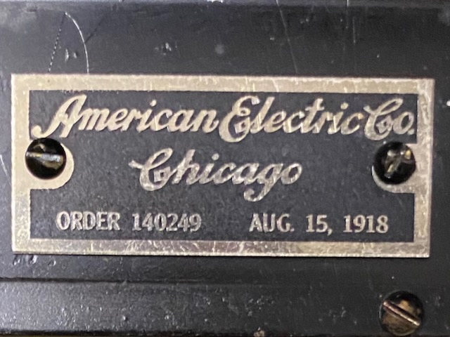
Manufacturer label, made by "American Electric" (which was later bought up by Automatic Electric [3]) in 1918.
Creative Commons Attribution-ShareAlike 4.0 International License