Repeating coils are 1:1 ratio transformers with typically 2x2 symmetrical windings on a magnetic core. The US signal corps calls these coils "Repeating coils" [8], British royal SC calls them "Superposing units" [9], in Germany they were called "Uebertrager" (~translator/transformer) [6] and in Switzerland "Cailho" [10], for the french engineer M. Cailho who described a usage for simplex circuits already in the 1880ies [22] [32]. These coils had two main uses in field line setups:
Before the availability of carrier frequency systems (portable field telephony carrier systems were first introduced in the 1940ies) the use of repeating coils was the only means to increase the capacity of lines. Even after introduction of carrier frequency technology it's use continued as it was a simple passive option.
From "Telephony" by McMeen and Miller [24]:
Phantom circuits are arrangements of telephone wires whereby more working, non-interfering telephone lines exist than there are sets of actual wires. When four wires are arranged to provide three metallic circuits for telephone purposes, two of the lines are physical circuits and one is a phantom circuit. Simplex and composite circuits are arrangements of wires whereby telephony and telegraphy can take place at the same time over the same wires without interference.
This superimposing of circuits allowed a doubling of the line capacity. A requirement for it to work well is that used 2-wire lines are well balanced. The different used setups are described in below table also detailing the different terms used by different countries signal corps.
| Technical details | Terms used per country | |||||||
|---|---|---|---|---|---|---|---|---|
| Diagrams [5] (Click for bigger image) | Wires | Earth return | Coils (per endpoint) | Telephony circuits | US [8] | British [9] [41] | German [7][11][12] | Swiss [10] |
|
2 | Y | 1 | 1 + 1* | Simplex | Phantom to earth | Simultan | Simplex |
|
4 | N | 2 | 3 | Phantom | Phantom | Vierer | Duplex |
|
4 | Y | 3 | 3 + 1* | Simplexed Phantom | Phantom to earth and Phantom | Vierer mit Simultan | Superphantom |
* The additional circuit in the "Simplex" and "Simplexed Phantom" setup is often described as to be used mainly for telegraphy (e.g. by the British SC used with the Fullerphone) and only in urgent cases for voice transmission as voice transmission quality maybe poor as earth return circuits are noisy.
These two US Army educational films from 1944 demonstrate very good how simplex/phantom circuits work and problems occurring on unbalanced paths.
Shortly after the invention of telephony in the mid 1870ies engineers thought about options to use the already existing and extensive telegraphy long distance network simultaneously for telephony. Telegraphy lines were then exclusively single wire with earth return. The first widespread used setup was the capacitive coupling of telephony onto telegraphy lines as described by François Van Rysselberghe in the early 1880ies [21]. This system had disadvantages with fast telegraphy systems like the Baudot system. To overcome these problems a better solutions was described by M. Cailho, then engineer at the "Administration des télégraphes français" in the late 1880ies [22]. This setup got rid of the capacitors but required 2 wire circuits plus earth return for simultaneous telegraphy and telephony, using the wire circuit for telephony and the on the midpoint of a coil (direct, no galvanic isolation) superimposed circuit for telegraphy. For that reason often simplex and phantom circuits have also been called "Cailho" circuits, and e.g. the Swiss Army simplex coil was called "Cailho" [32]. Up to the introduction of carrier frequency transmission systems long distance trunks would always use phantom circuits as the long distance lines were the most expensive part of a telephony network. On civil networks early carrier frequency systems with 4 channels were available in the 20ies (later on coax carrier frequency systems up to 13200 4kHz analog voice channels were possible), armies started to use carrier frequency systems (which had first to be available at least somewhat portable) first in the 40ies.
| (Click for bigger image) | Country | Name | Year | DC impedance per winding [Ohm] | Size | Weight |
|---|---|---|---|---|---|---|
 |
Switzerland | Cailho | ~1914 | 23 | 125x100x260mm | 4.25kg |
 |
USA | Coil C-161 | ~1935 | 21 | 126x80x65mm | 1.3kg |
 |
Germany | Uebertrager, Schnurlos | ~1935 | 21 | 122x47x178mm | 1.7kg |
 |
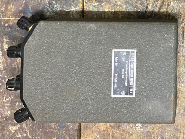
Germany (DDR) | Ortsleitungsringübertrager 52 | 1952 | 31.5 | 115x52x192mm | 2kg |
 |
Germany (BRD) | Ringübertrager (NSN 5950-12-125-3592) |
~1955 | 10 | 105x62x135 | 1.65kg |
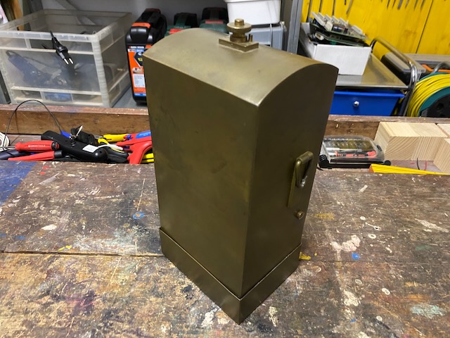
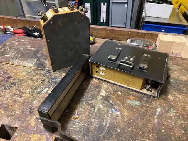
The first "Cailhos" in brass case were ordered in 1914 from Hasler [32]. The coil used is provided by BTMC (Bell Antwerpen) and corresponds to the WE 27-A repeating coil [23]. The "Cailho" can be configured by moveable links to be used as "Translator" (corresponding to a repeating coil setup) to be used to connect between different line types (e.g. 2-wire to 1-wire with earth return) or to be used as "Cailho", to use the simplex and phantom circuit setup as intended by Cailho without galvanic isolation.
"Cailhos" were in use up into at least the 50ies. In the early 50ies the "Duplexkasten" was introduced, a box with three fix wired repeating coils to connect directly to the F-4 cable (US surplus WC-548 «Spiral Four») [13].
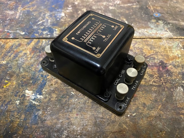
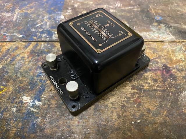
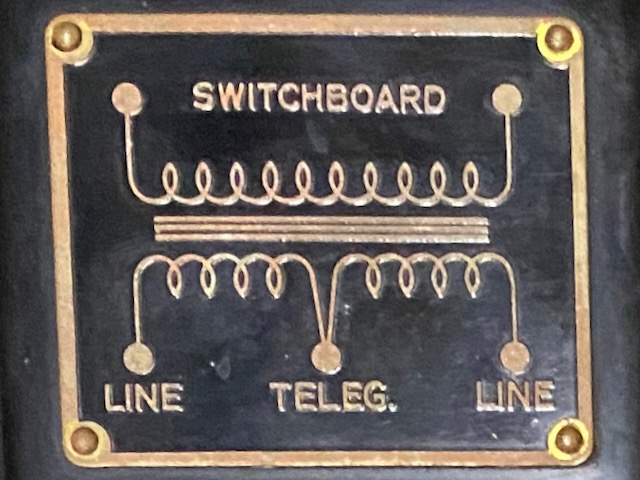
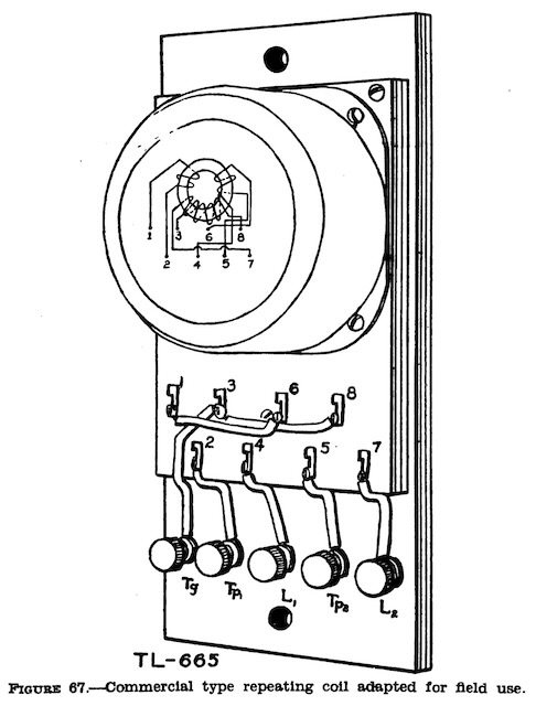
The US Coil C-161 is also mounted fix in certain switchboards (BD-71/72) [8]. It is fix configured to have a "Switchboard" side, a "Line" side and a telegraphy terminal. U.S signal corps documents also mention an earlier bigger coil C-75 and the use of commercial coils like the WE 27-A [8].
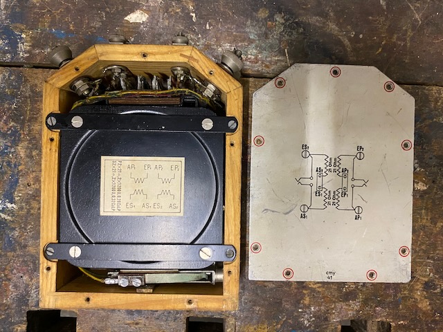
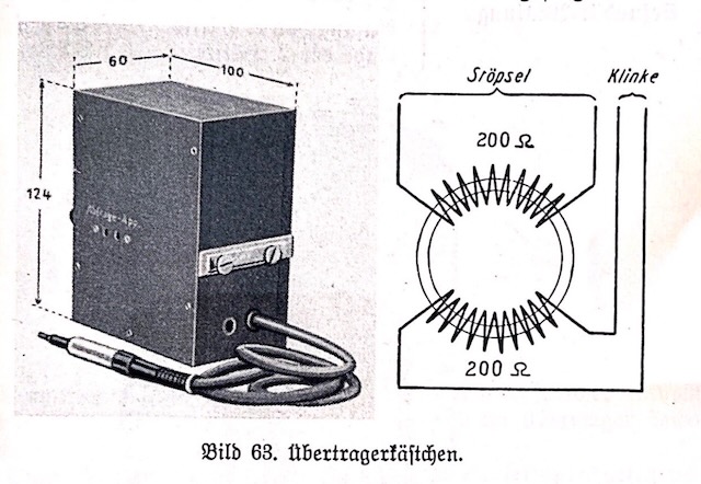
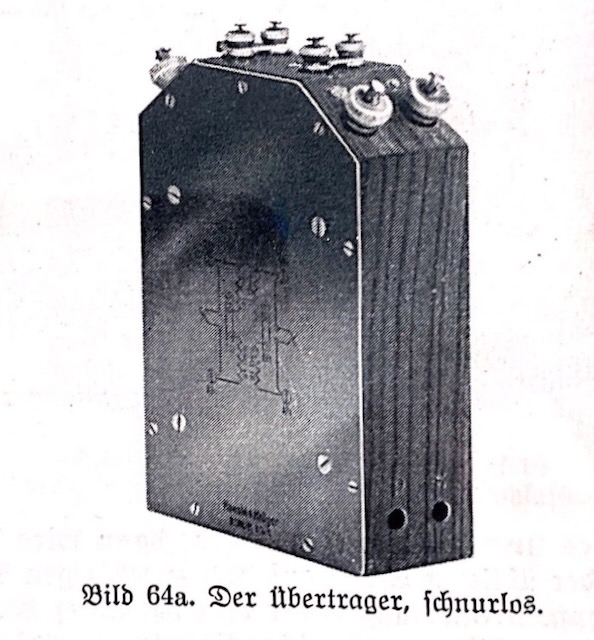
The "Uebertrager, Schnurlos" (Repeating Coil, Cordless) is called that because its predecessor the "Uebertragerkästchen" had a fix connected cord [3][42]. The "Uebertragerkästchen" could only be used to connect between 2-wire and 1-wire lines, whereas the "Uebertrager, Schnurlos" can be used for that and for simplex/phantom setups. All 4 coils have separate binding posts but the midpoints are per default connected by a moveable latch. The main primary/secondary connections are also connected to a socket compatible with switchboard cord plugs. The midpoint latch can be opened to e.g. put in capacitors if the device would be used to connect to a CB line (to block the CB DC current) [4].
The east german "Ortsleitungsübertrager 52" keeps the form and the dimensions of the "Uebertrager, Schnurlos" but is built as metal box instead of a wooden frame. The circuit setup is identical to the "Uebertrager, Schnurlos" including the primary/secondary sockets. The coils specifications are similar but not identical to the "Uebertrager, Schnurlos".
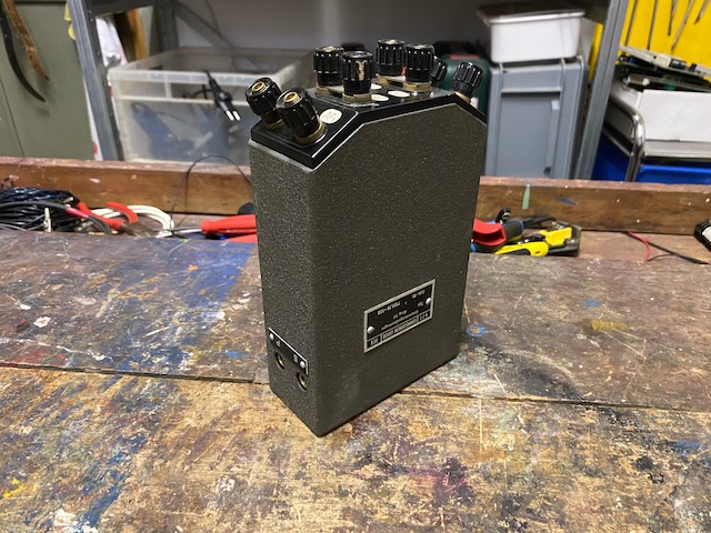
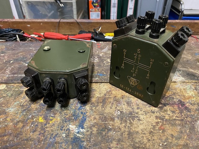
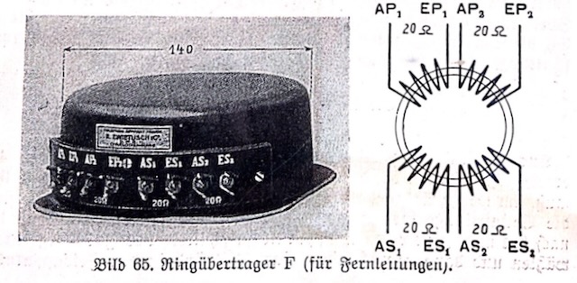
The west german "Ringübertrager" also keeps the form of the "Uebertrager, Schnurlos" but is smaller and also built as metal box instead of a wooden frame. The coil is cast in directly into the box. The circuit setup is identical to the "Uebertrager, Schnurlos" but without the primary/secondary sockets. The coils specifications are similar but not identical to the "Uebertrager, Schnurlos".
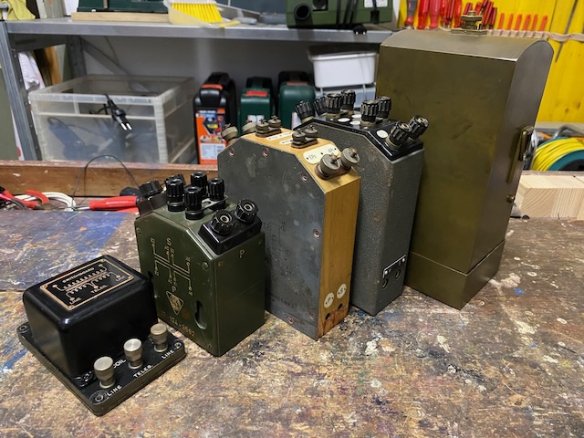
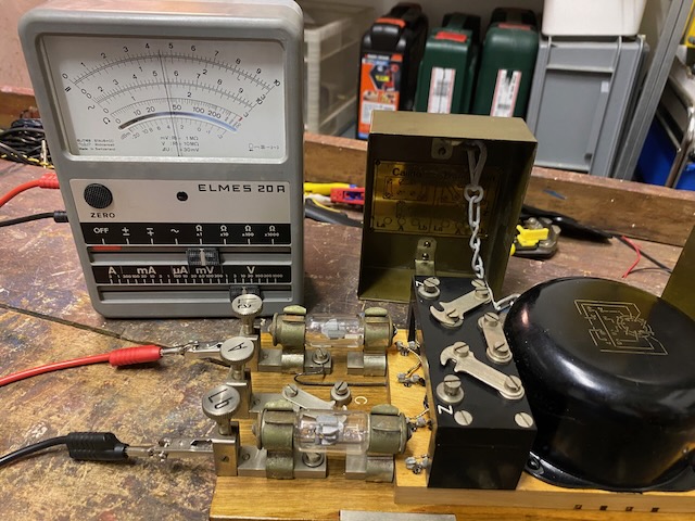
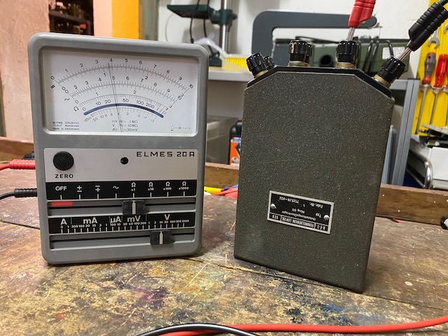
From left to right:
US Coil C-161 (~1935),
West German "Ringübertrager" (~1955),
Nazi German "Uebertrager, Schnurlos" (~1935),
East German "Ortsleitungsringübertrager 52" (1952),
Swiss "Cailho" (~1914).
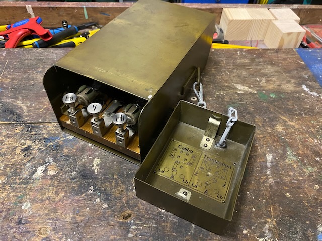
Brass box.
Bottom opened to access binding posts.
The lid can be secured to the side to not get lost.
Inside the lid a diagram showing the two operation mode settings: "Cailho", "Translation".
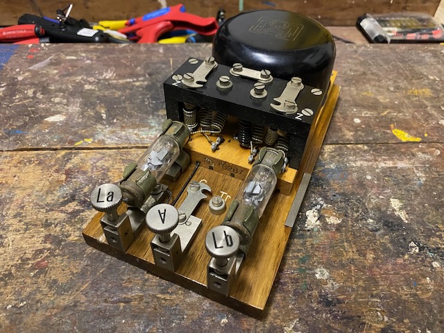
Removed from the box.
All mounted to a wood main board.
Lightning protectors.
The BTMC product ID for the coil is AD16287.
Latches mounted in mode "Cailho".
Bottom of board.

Latches mounted in mode "Translation".
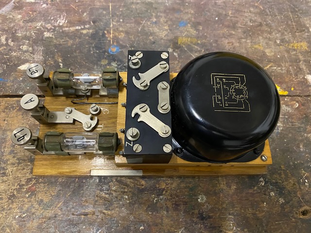
Neat.
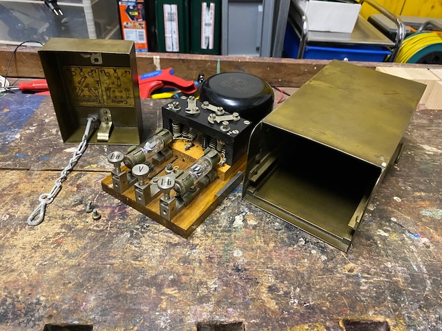
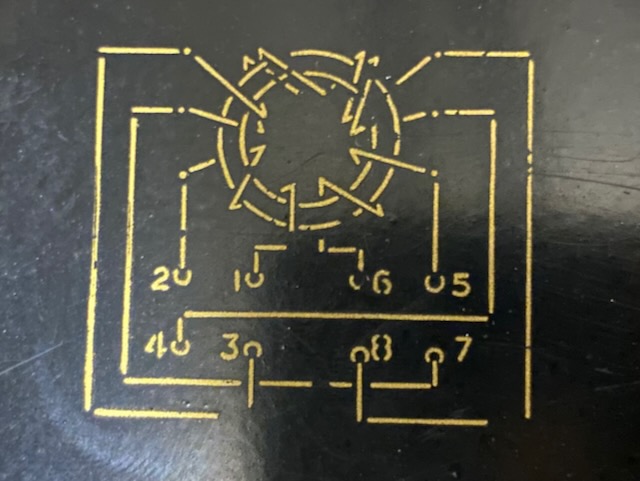
Diagram on coil.
Inside the lid a diagram showing the two operation mode settings: "Cailho", "Translation".
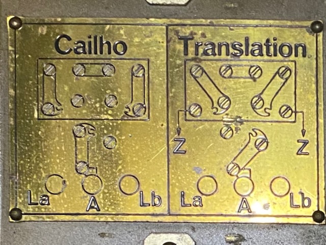
Diagram of modes [25].
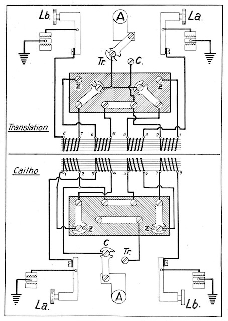
DC resistance mode "Cailho" (all 4 windings) = 4 x 23 Ohm.
.jpeg)
DC resistance mode "Translation" (2 windings) = 2 x 23 Ohm.
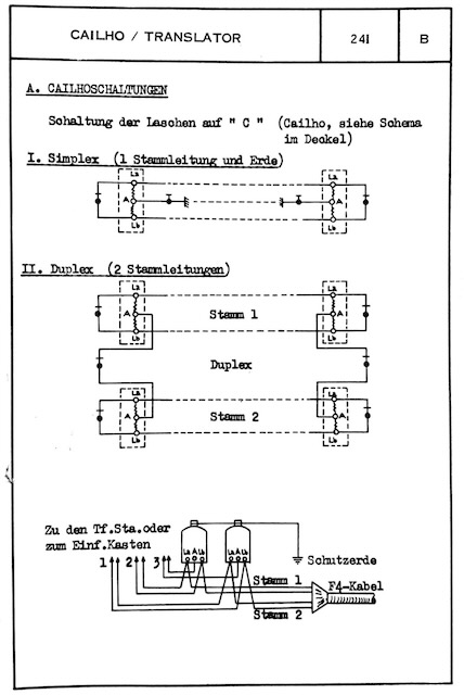
"Cailho" setups ("Simplex", "Duplex") from [10].
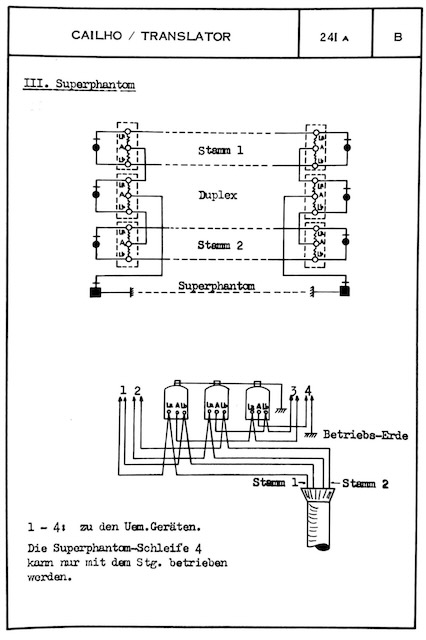
"Superphantom" from [10].
"Die Superphanton-Schleife 4 kann nur mit dem Stg. betrieben werden." (Only use the "Superphantom" circuit #4 for telegrahy).
"Translation" setups (2-wire to 1-wire; civil line to field line) from [10].
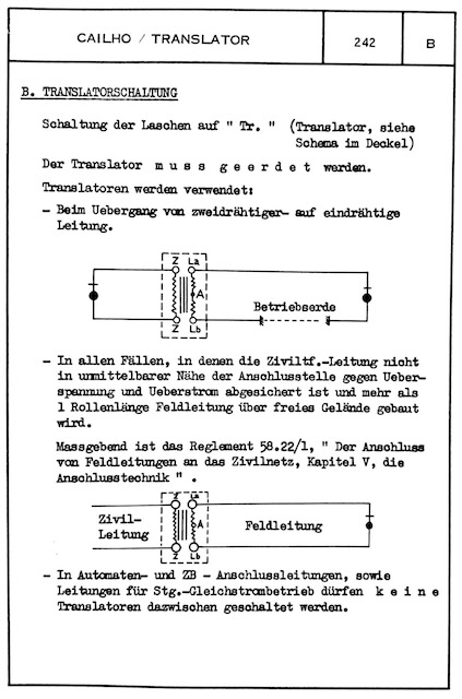
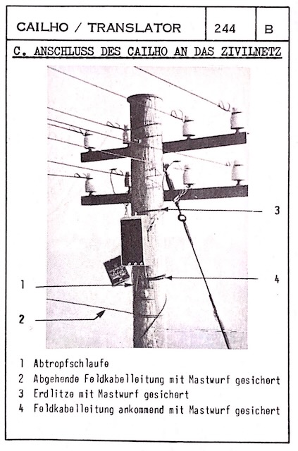
How to mount the "Cailho" box when connecting to a civil line from [10].
Coil under metallic hood on fibre board.
Line side.
Switchboard side.
Bottom.
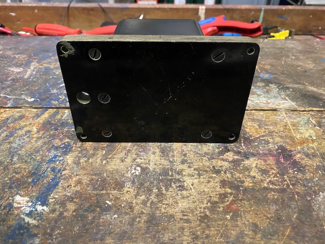
Diagram on hood.
One winding = 21 Ohms DC resistance.
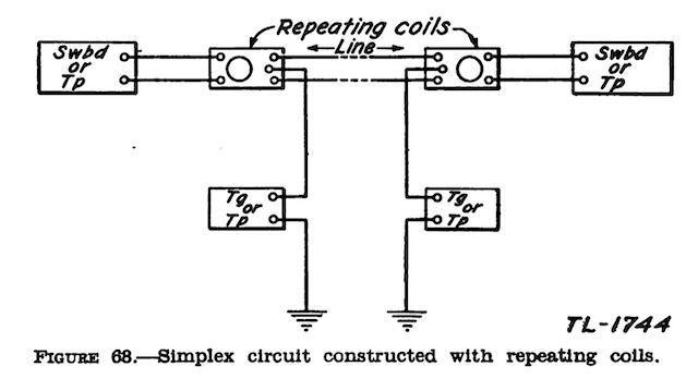
Simplex circuit from [8].
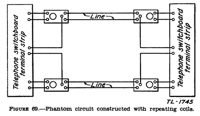
Phantom circuit from [8].
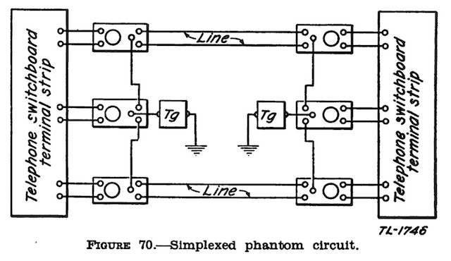
Simplexed phantom circuit from [8].
Commercial coil (eg. WE 27-A repeating coil [23]) "adapted" for field use by mounting on board and wiring respectively to binding posts (Note: more or less what the Swiss "Cailho" is) from [8].
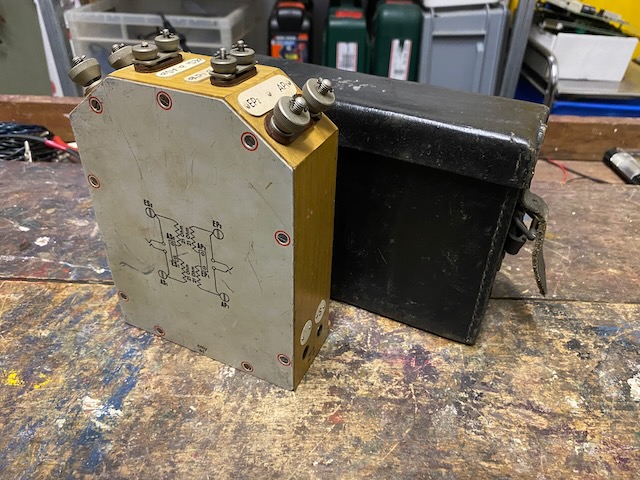
The "Uebertrager, Schnurlos" came in a nice leather transport box.
The one out of the Box was made bei "Telefonbau und Normalzeit", no year outside or inside of the box and no acceptance stamp, maybe was in civil use, or made post WWII.
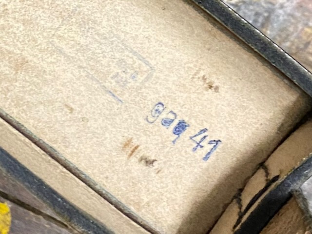
The other one is made by "cmy" (= Erka, Berlin) in 1941.
Made by "cmy" (= Erka, Berlin) in 1941.
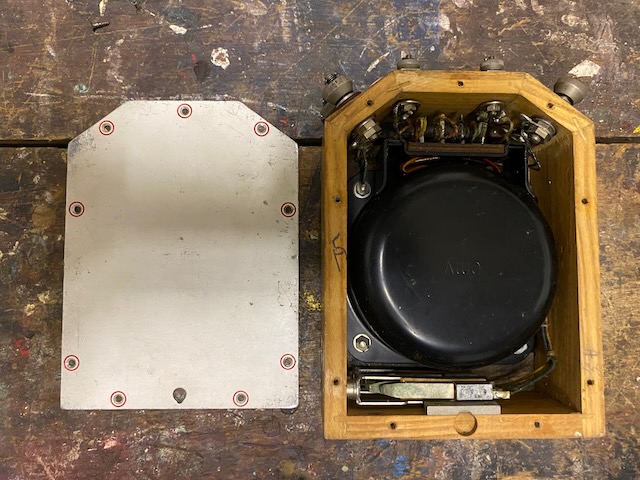
The front lid can be removed.
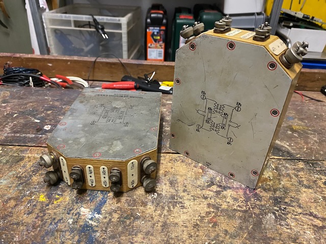
Diagram on the lid.
Telefonbau und Normalzeit and "cmy".
"P"rimary and "S"econdary cord socket.
Acceptance stamp below sockets.

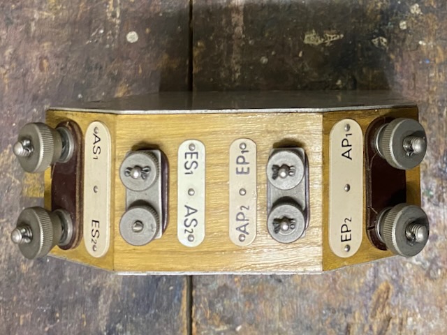
Binding posts on top.
Right primary side, left secondary side.
The coil midpoints are connected with latches.
Frontside open.
Backside open.
Coil also made by "cmy".
The lid on the backside has a hole to hang the coil on a nail on a wall for instance.
The leather box was made by "gaq" in 1941 (Unknown to me "camouflaged manufacturer ID").
One winding = 21 Ohms DC resistance, as specified.

"Translation" setup (2-wire to 1-wire) [5].
![]()
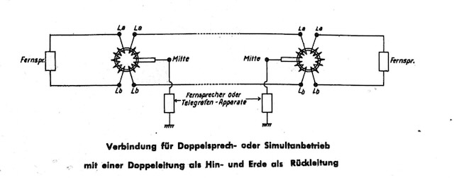
"Verbindung für Doppelsprech- oder Simultanbetrieb mit einer Doppeleitung als Hin- und Erde als Rückleitung" (Double talk or simultaneous operation with a 2-wire line as the outgoing line and earth as the return line) [5].
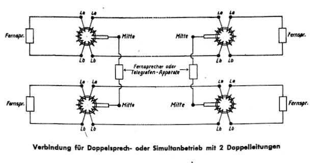
"Verbindung für Doppelsprech- oder Simultanbetrieb mit 2 Doppelleitungen" (Double talk or simultaneous operation with 2 2-wire lines) [5].
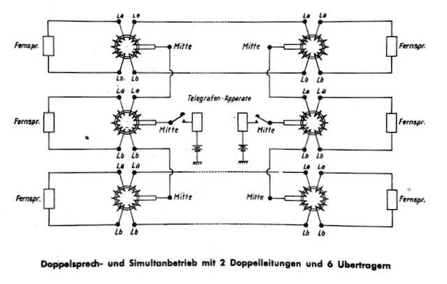
"Doppelsprech- und Simultanbetrieb mit 2 Doppelleitungen und 6 Ubertragern" (Double talk and simultaneous operation with 2 2-wire lines and 6 repeating coils) [5].
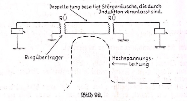
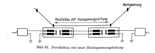
Using repeating coils when connecting 1-wire to 2-wire connection along a high voltage line to suppress ingress noise [3].
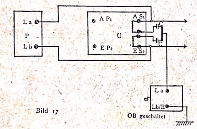
Connecting an LB circuit to a civil CB line using a repeating coil with capacitors inserted at the midpoint [4].
"Uebertragerkästchen"; with cord, hence the other "Uebertrager" is called "Schnurlos" (= without cord) [3].
"Uebertrager, Schnurlos" [3].
"Reichspost" repeating coils have also been used [3].
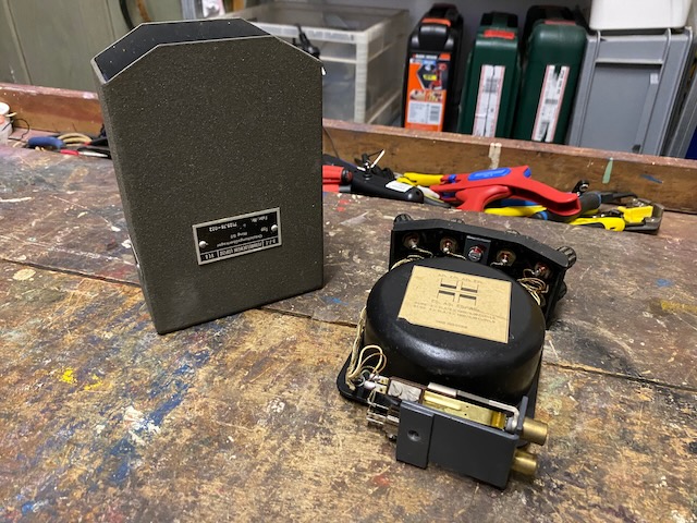
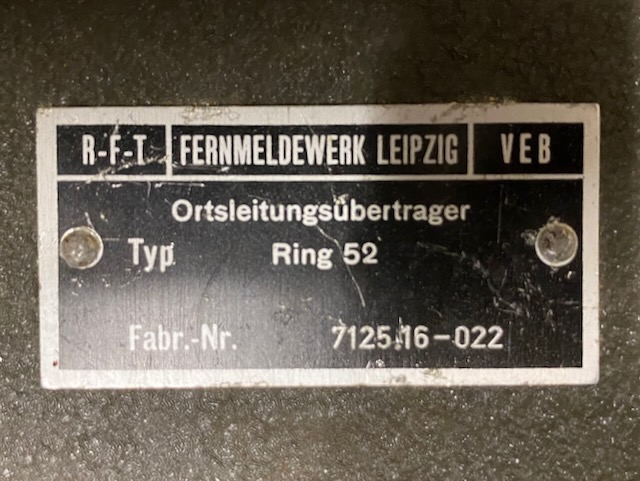
Made by R-F-T Leipzig.
Same form and setup as the "Uebertrager Schnurlos", but metallic box instead of wood frame.
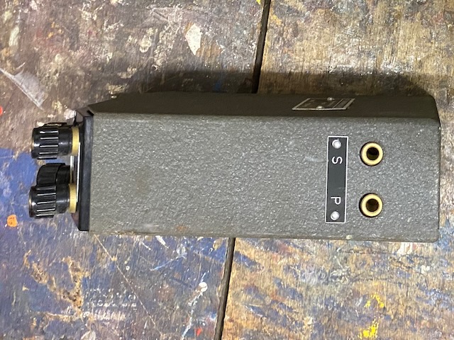
Front.
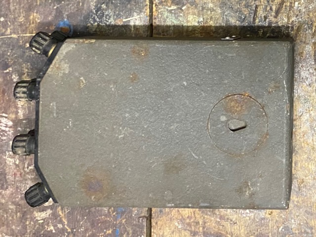
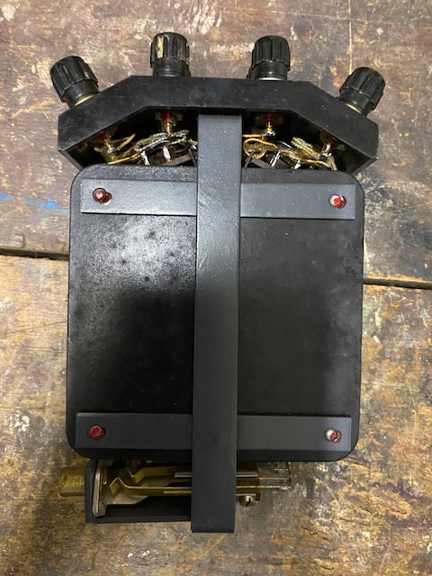
Back, also with possibility to hang on a wall.
"P"rimary and "S"econdary cord socket.
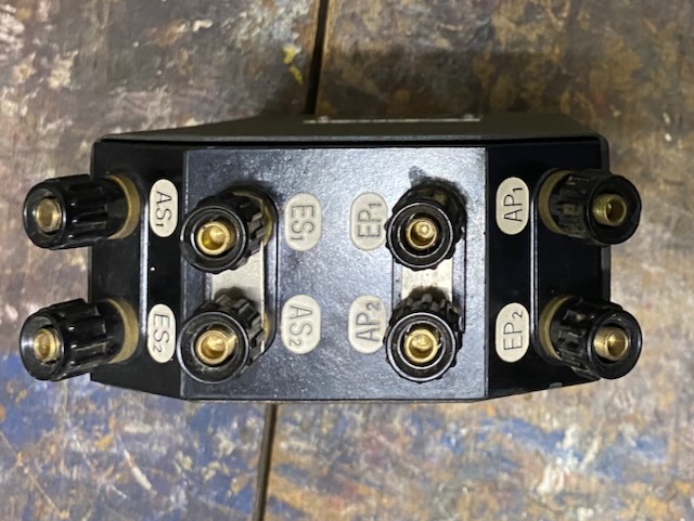
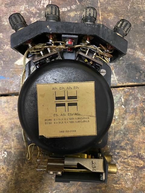
Binding posts on top.
Right primary side, left secondary side.
The coil midpoints are connected with latches.
Open.
Open front.
31.5 Ohm DC resistance.
Open back.
Label.
One winding = 31.5 Ohms DC resistance, as specified.
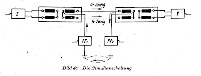
"Simultanschaltung" (Circuit for simultaneous operation) [11].
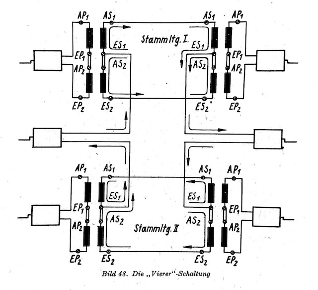
"Vierer-Schaltung" (Circuit for "quad" operation) [11].
"Übergang von Doppel- auf Einfachleitung" (Transition from double to single line)[11].
![]()
"Verbindung einer Einfach- mit Doppelleitung über einen Ringübertrager an der Vermittlung" (Connection of a single line to a double line via a repeating coil at the switchboard)[11].
![]()
"Parallelbau mit einer Hochspannungsleitung" (Parallel construction with a high-voltage line)[11].
Same form as the "Uebertrager Schnurlos", but smaller, metallic box and no cord sockets.
These can be stacked using the connections on the sides.
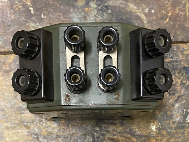
Binding posts on top.
The binding posts include banana sockets.
The coil midpoints are connected with latches.
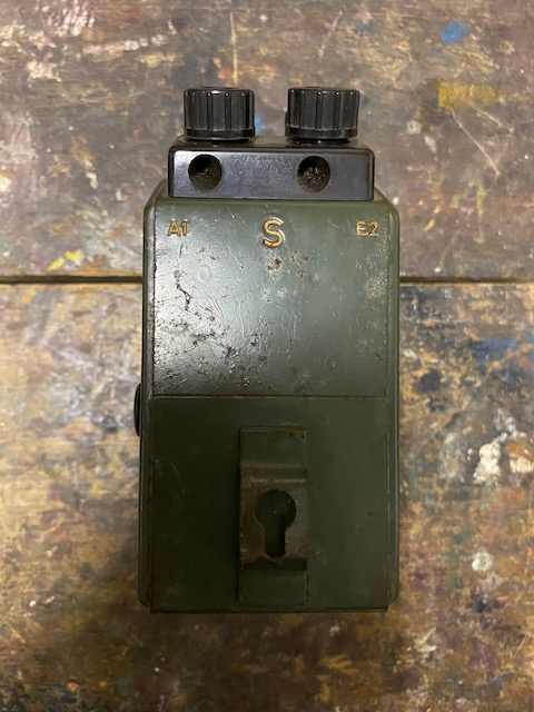
Secondary side.
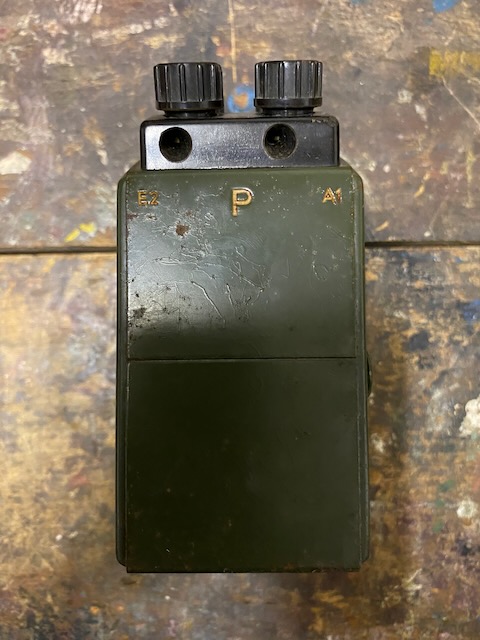
Primary side.
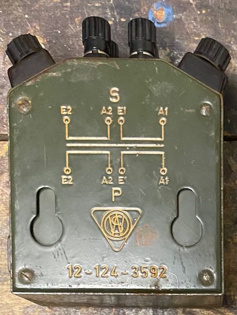
Back side with "diagram".
Made by "Wilhlem Sedlbauer, München", Sedlbauer also made "Uebertrager, Schnurlos".
Back lid removed, the coil is directly molded into the case.
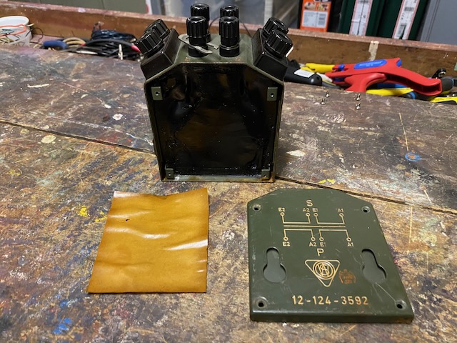
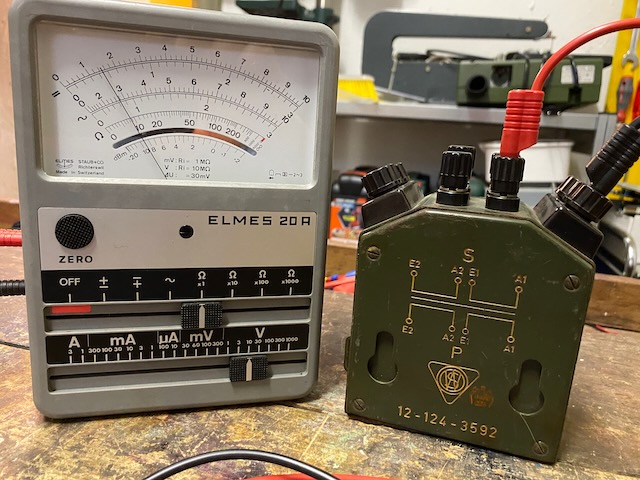
One winding = 10 Ohms DC resistance.
Creative Commons Attribution-ShareAlike 4.0 International License