Find more details on Swiss field telephone history on the Swiss Army Field Telephones Timeline.
The Swiss Army field telephone "FTf 41: Feldtelefon Modell 1941" was developed by Autophon A.G., Solothurn, in the early 40ies. The goal was to replace the current "Feldtelefon" introduced in 1909 (and the only slightly updated version "Feldtelefon 1925") with technology equivalent to the Armeetelefon Modell 1932 [1], [2]. The resulting instrument is a combination of the electrical setup of the ATf 32 with the Form factor and sturdiness of the FTf 09/25.
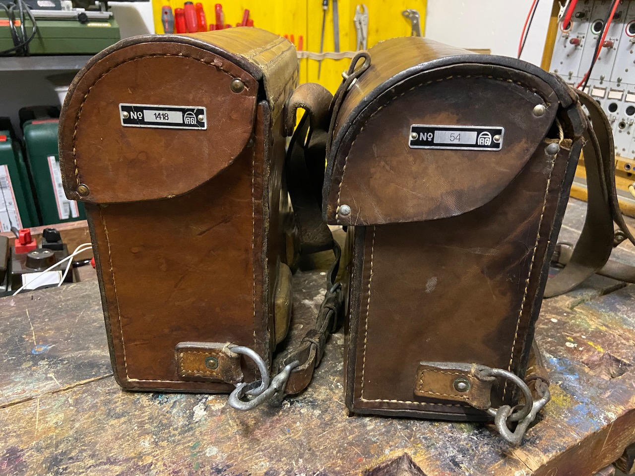
In comparison to the ATf from which more than 12000 were built much less were built of the FTf 41. The most authoritative sources ([1], [4]) disagree about the numbers and years, [1] mentions 636 pcs. made from 1942 to 1946, and [4] mentions 900 from 1942 to 1944 (sic). The instrument with the lowest inventory/serial ID I own is 54 made in 1942, the highest I own has ID 1418 made in 1946. As there were two generations of FTf 41 (More details below) it might well be that the numbering is not continuous. I would estimate that at least 900 were made between 1942 and 1946, as then in 1947 the slightly updated FTf 47 was introduced.
FTf 41 was exclusively built by Autophon. There were two slightly different series. Electrically and feature wise they were identical. On the later series the mechanical construction of the lid support was improved significantly, for more details see both models in the gallery below. The magneto of the early models was sourced from Albiswerk, the buzzer was sourced from Albiswerk for the complete series.
Short description from the Swiss army infantry signalling handbook (1942, [2]):
The field telephone Mod. 41 combines the advantages of the field telephone Mod. 25 and the army telephone Mod. 32. It replaces the army phone for the infantry. Circuits, main components and construction were largely taken over from the army telephone, the type of installation from the field telephone Mod. 25. Circuit and cabling diagrams are attached to the apparatus cover.
Changes compared to the field telephone Mod. 1925: Similar circuitry and construction to the army phone. Side-mounted patch sockets that can be operated when the device lid is closed. The sockets are protected by a leather cover with snap button closure. The inductor is installed in the main chassis. Three slits in the leather knapsack on the side of the clamps prevent short circuits between the end loops and allow easy feeding of lines and earth when the cover is closed. The position of the microphone on the fork is clearly determined by the inscription telephone-microphone. When the lid is closed and the handset is hung up, the fork is pressed down by a device fitted in the lid, thus interrupting the circuit. The plug cord is stored in the lid. The design and attachment of the insert box enable quick installation and removal and prevent the insert box from getting stuck in the knapsack.
Changes compared to the Army Telephone Mod. 32: The leather knapsack offers better protection for field service than a wooden case. The carrying straps are firmly mounted, do not hang out and allows the device to be carried comfortably. The handle of the microphone contains a talk button. The buzzer button is also mounted above the talk button. The attachment of these two buttons requires an increase in the number of pins on the connector from 4 to 6. The shape of the headphone and microphone press bodies have been changed in the sense that they can be operated under the steel helmet. A hook allows the handset to be hung up. The hook is omitted from the metal sleeves of the plugs to the headphones and handset. The protruding edge at the top allows the plug to be pulled out easily. The construction of the fork is adapted to the leather knapsack. The fork base piece is used to store the headphones and inductor crank. The lid of the insert box is on top. It can be opened after loosening a captive screw. When the cover is opened, the field elements, fuses and spare fuses are accessible. It is therefore not necessary to remove the chassis to replace these parts. The connection terminals are attached at the top. The chassis-mounted line test button allows line testing.
Some notes on above text:
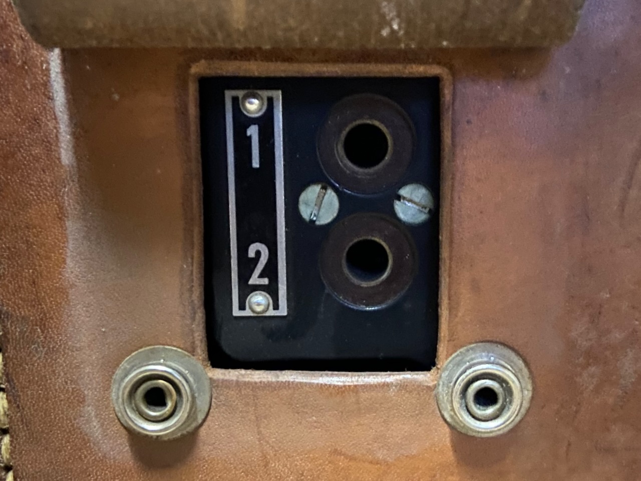
Line sockets allow to build a small field switchboard with multiple FTf 41 [3]. Socket #1 is to be used to connect the instrument to a line from another instrument, socket #2 to connect another instrument to the local line (the local instrument is disconnected from the line when a plug is inserted into socket #2). The required patch cord is available in every FTf 41.
For connection to a CB/Aut. network the Wählerzusatz 32 from the ATf 32 can be used.
When the top lid is open the telephone is operated by means of the hookswitch for LB and CB operations (The push to talk lever on the handset is bridged by the hookswitch). When the top lid is closed the hook switch is pressed into "on hook" als without handset. Then the handset can be used with the push to talk lever, as on other typical field telephones.
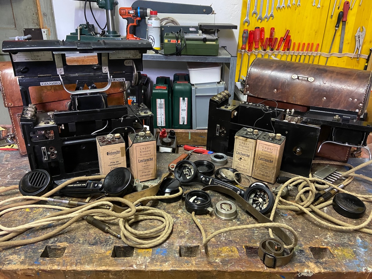
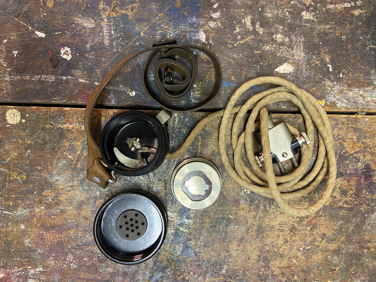
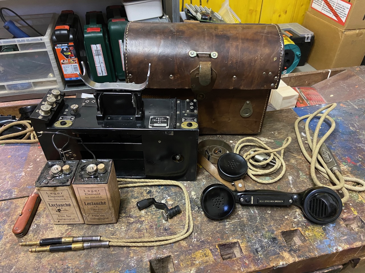
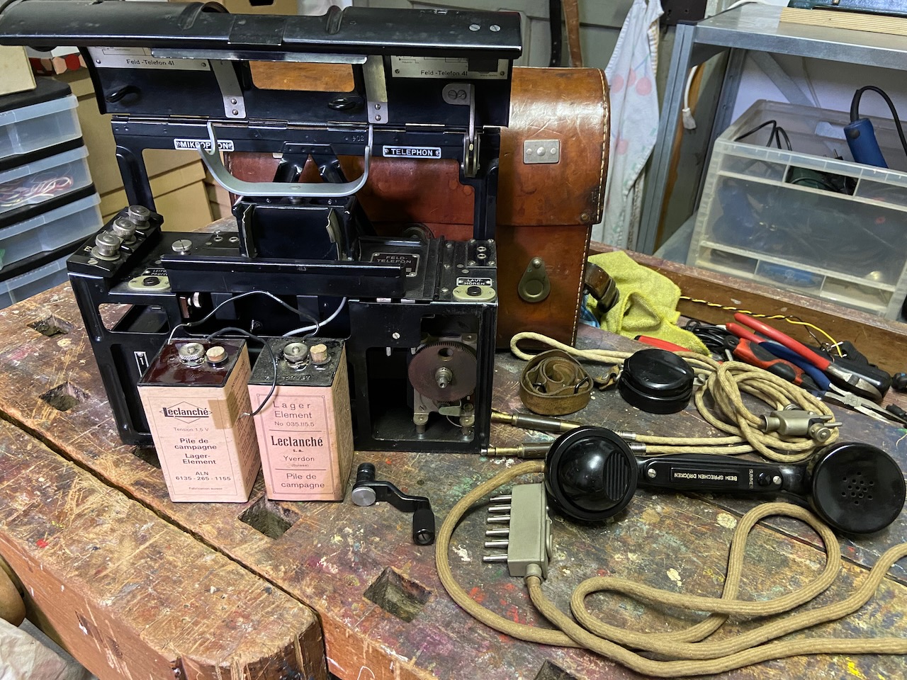
Disassembled.
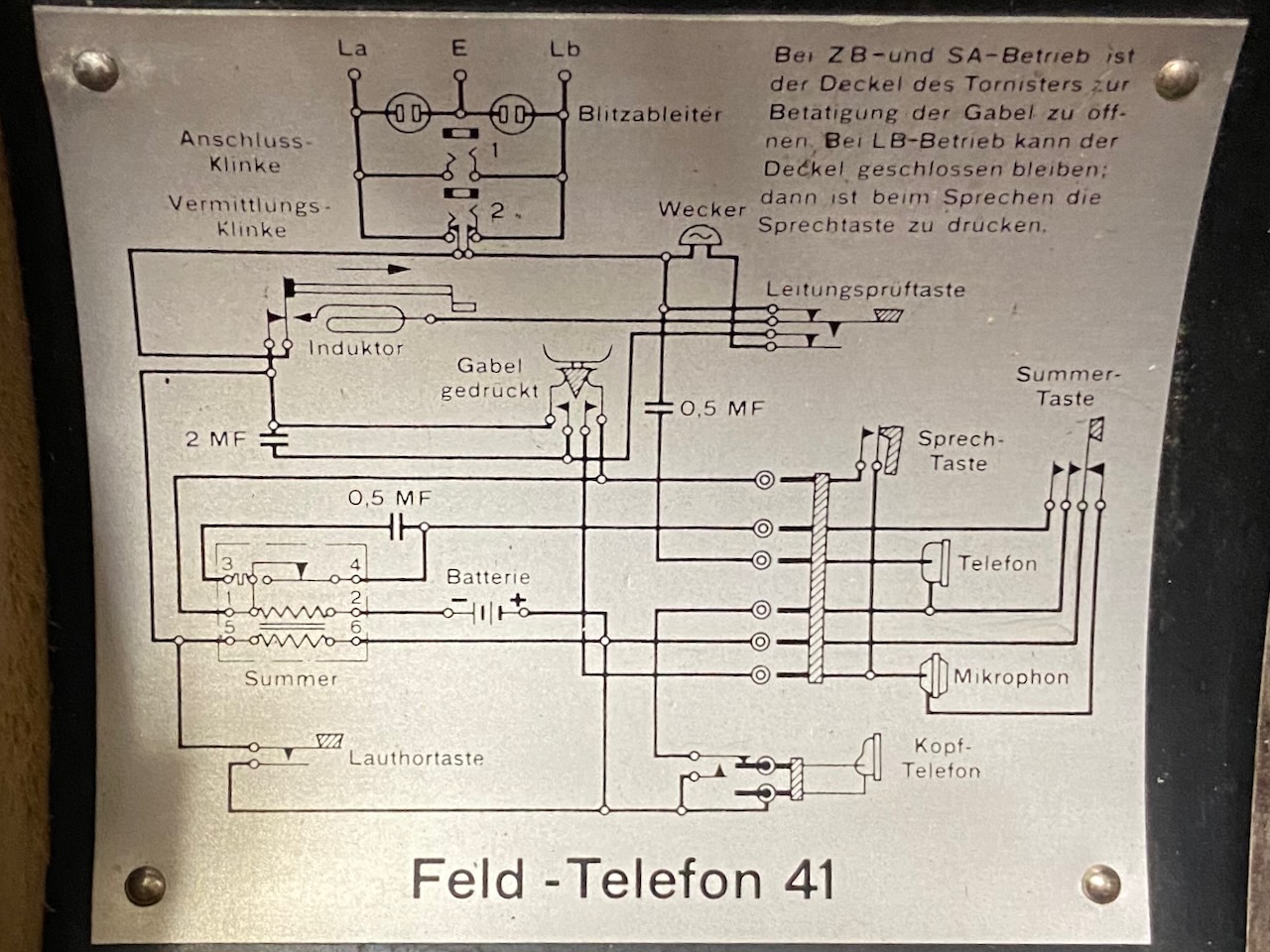
Electrical diagram inside Lid (The diagrams are identical in the early and late series FTf 41).
The electrical setup is straight forward and mostly identical to the ATf 32 (apart from the push to talk lever in the handses).
The text top right says: "For CB and CB/Aut. operation the lid of the knapsack stays open to operate the fork. The cover can remain closed during LB operation: then the talk button must be pressed when speaking.
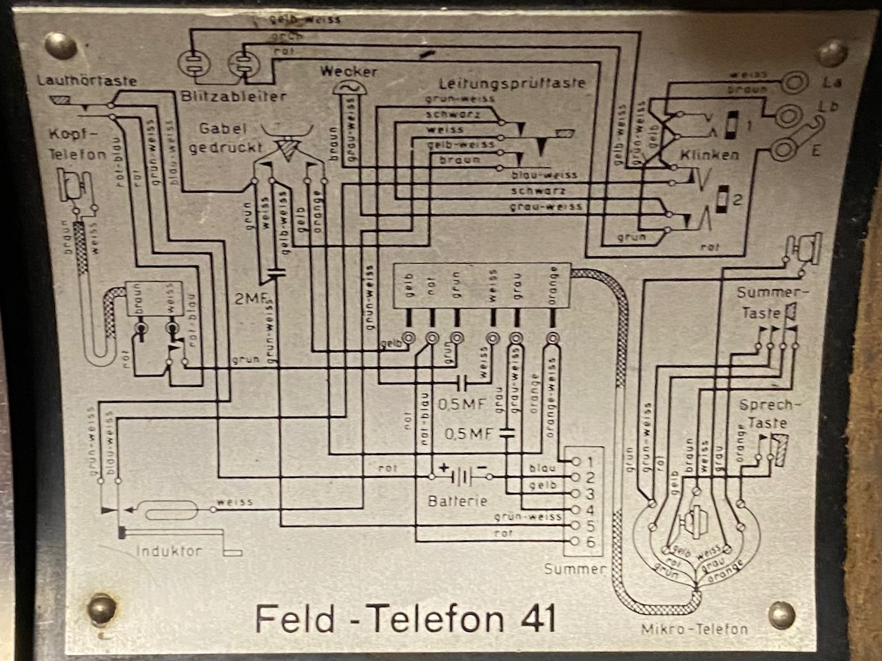
Wiring diagram inside Lid (The diagrams are identical in the early and late series FTf 41).
The bakelite handset is based on the Swiss PTT type 31 (with added P.T.T. and buzzer button) using the same size of RX and TX modules.
On the TX side originally an "Lorenz" type module was used, it was later upgraded to Swiss PTT type 46 modules (with adapter rings).
The handset is also made leaner on the RX side to be able to use with helmet on.
The plug is similar to the ATf 32 plug but with 6 instead of 4 prongs (additional prongs for the P.T.T. and buzzer in handset).
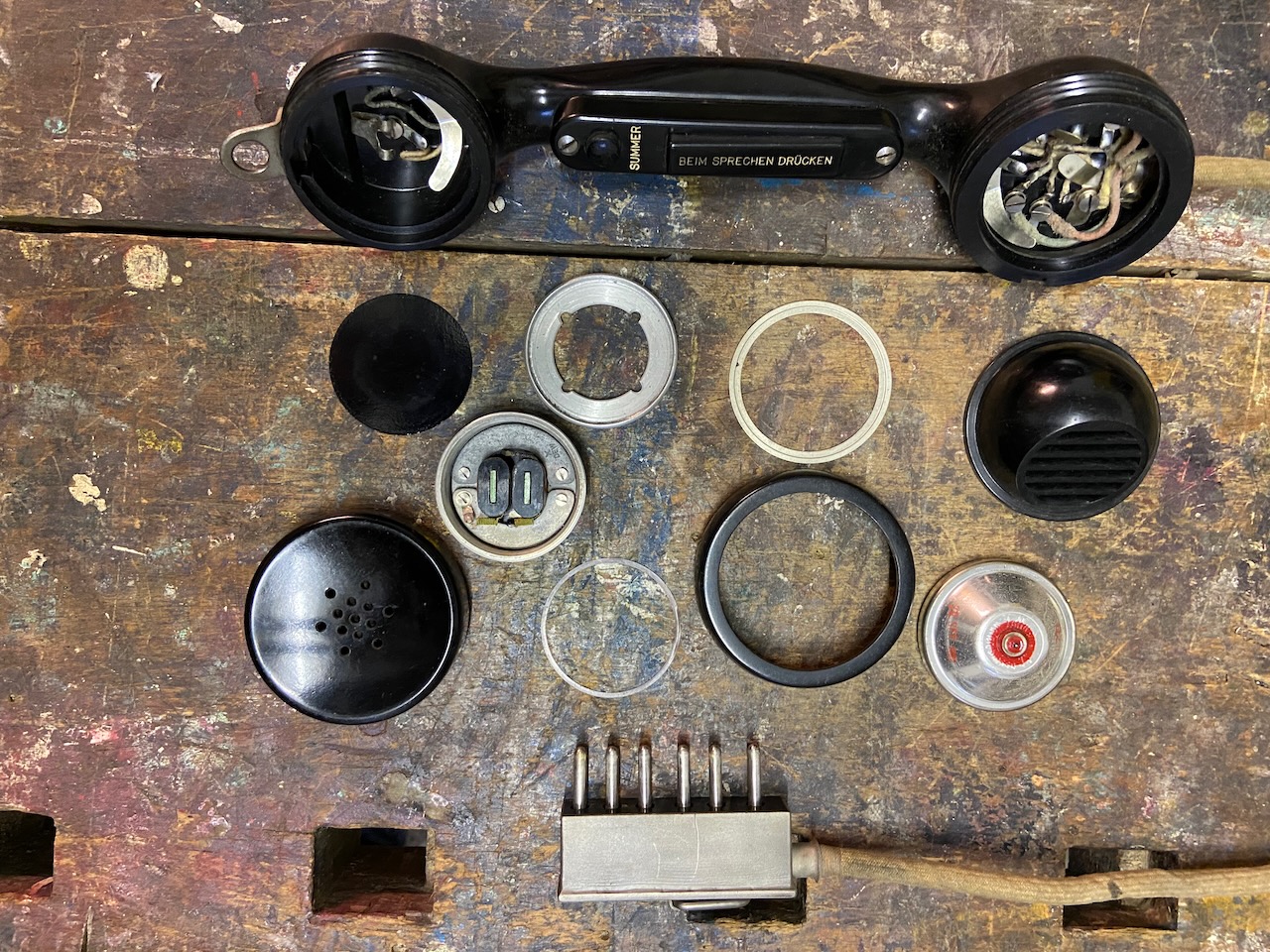
The headset uses the same RX module as the handset.
The connector provides binding posts for direct line connections, to use as sender and receiver ins emergencies or as lightweight line troubleshooting telephone.
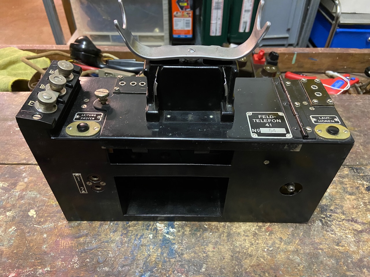
Early series body.
Left button: "Line test".
Right button: "Loudness" (shortens RX circuit).
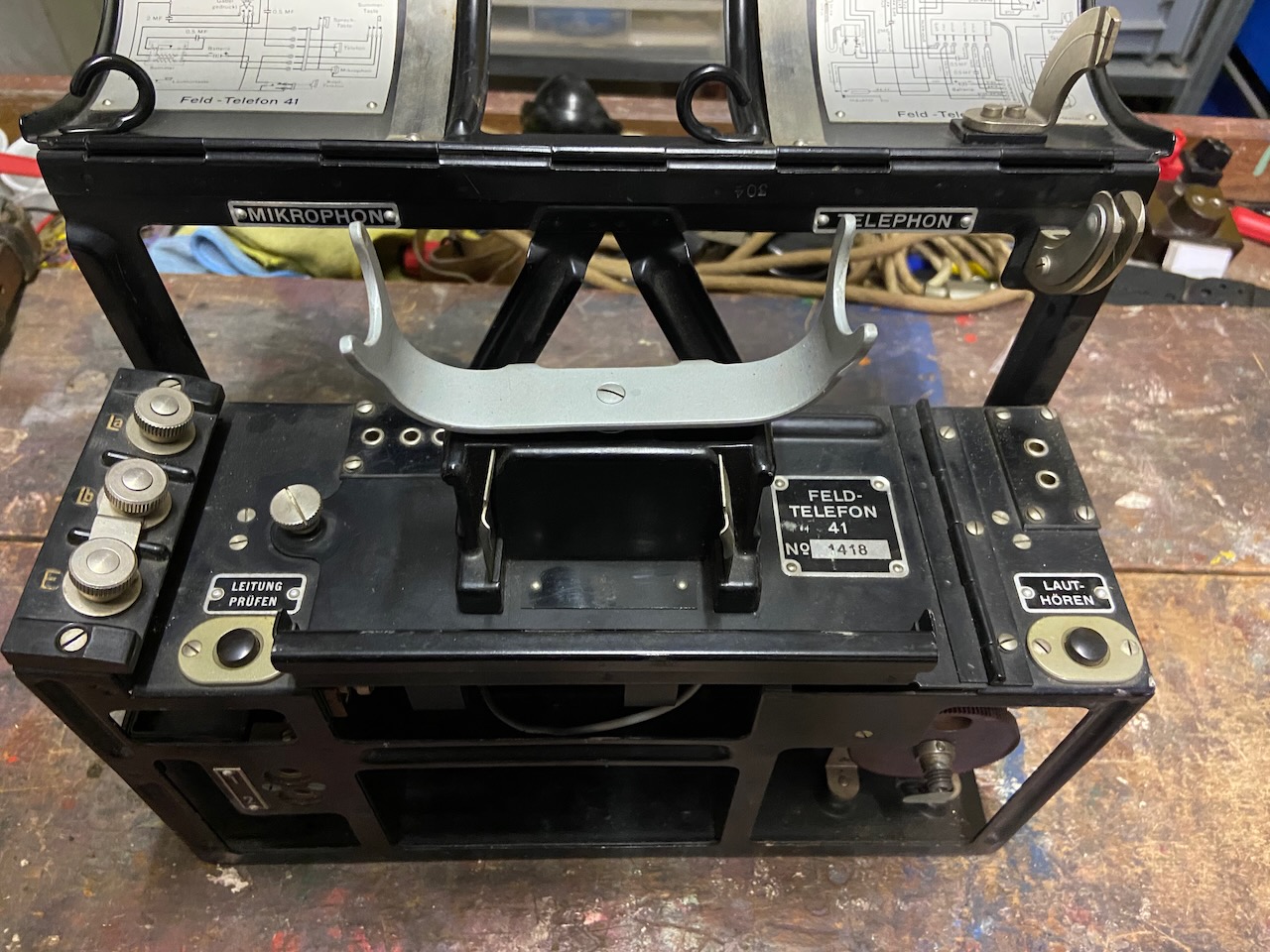
Late series body.
The bottom frame is built lighter (and from an aluminum alloy, not iron like the early series), but extended with the lid support.
"Mikrophon" and "Telephone" indicate the handset position on the cradle.
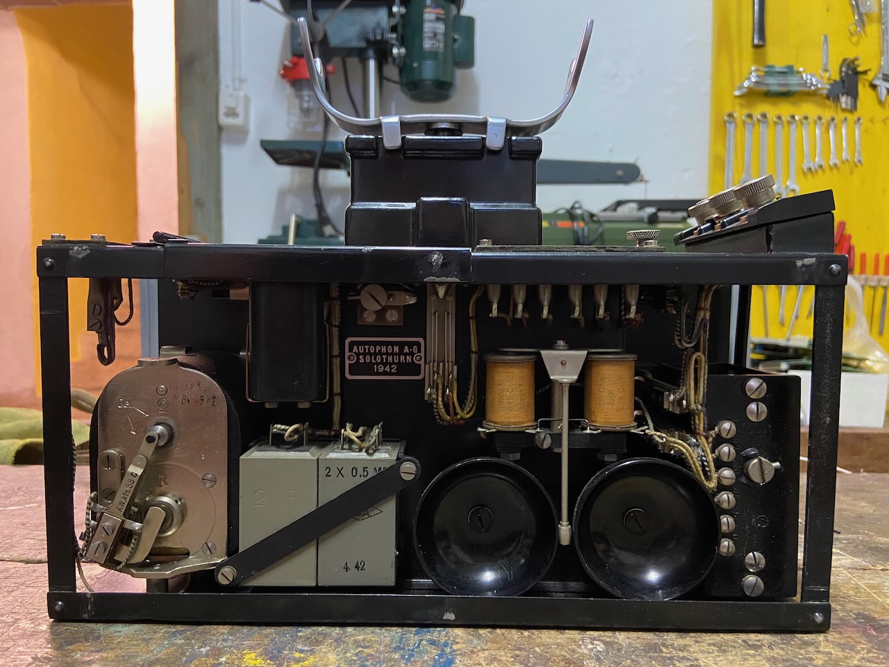
Early series back.
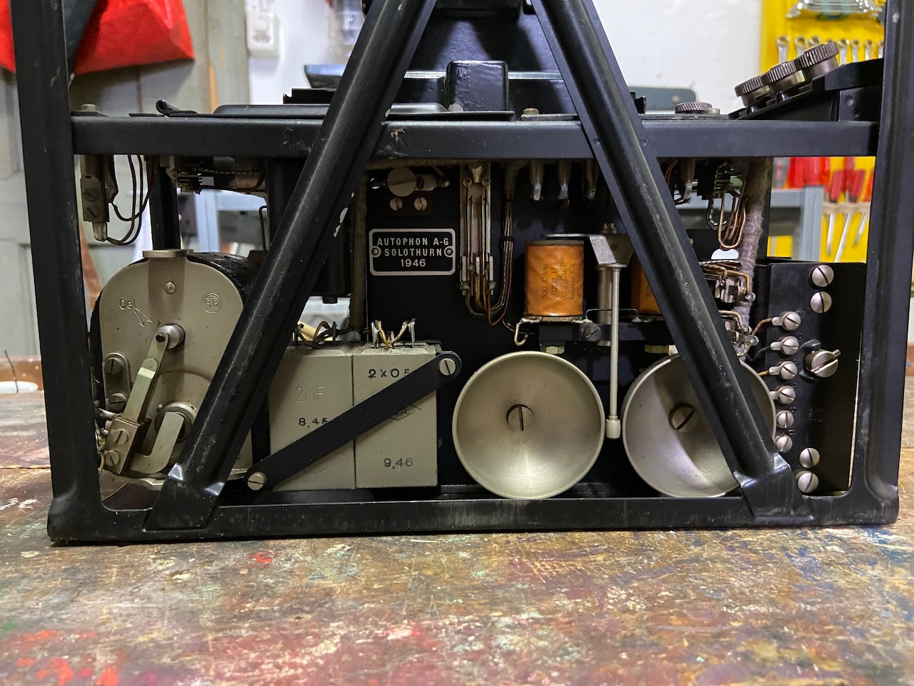
Made in 1942.
Magneto and Buzzer are sourced from Albiswerk ("Siemens Switzerland").
Late series back.
Made in 1946.
Buzzer still sourced from Albiswerk ("Siemens Switzerland"), but now magneto made by Autophon (1:1 copy of the Albiswerk part).
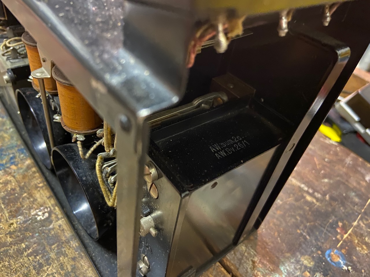
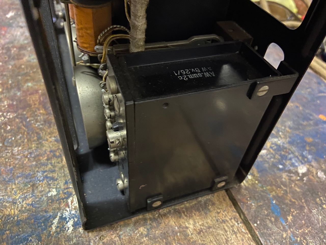
Early series.
The Albiswerk Buzzer AW.Bv.26/1, which includes the speech coil.
The same buzzer was used in the ATf 32 and the PiZ 37.
Late series.
Same buzzer.
Early series neatly lined up for mounting.
Early series neatly lined up for mounting.
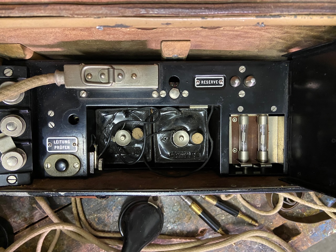
Early series, battery compartment open.
On the right the gas filled lightning arrestors, nearby the neatly marked "Reserve" spare arrestors.
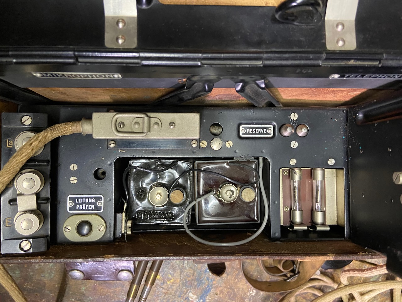
Late series, battery compartment open.
Identical to early series.
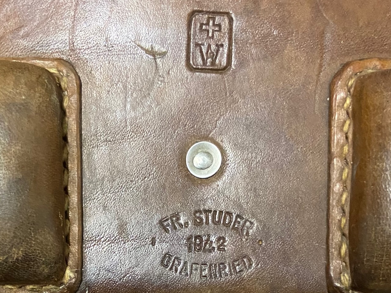
Knapsack 1942, made by Fr. Studer from Grafenried.
Not sure about the acceptance mark, probably "W" is the ID of the accepting inspector.
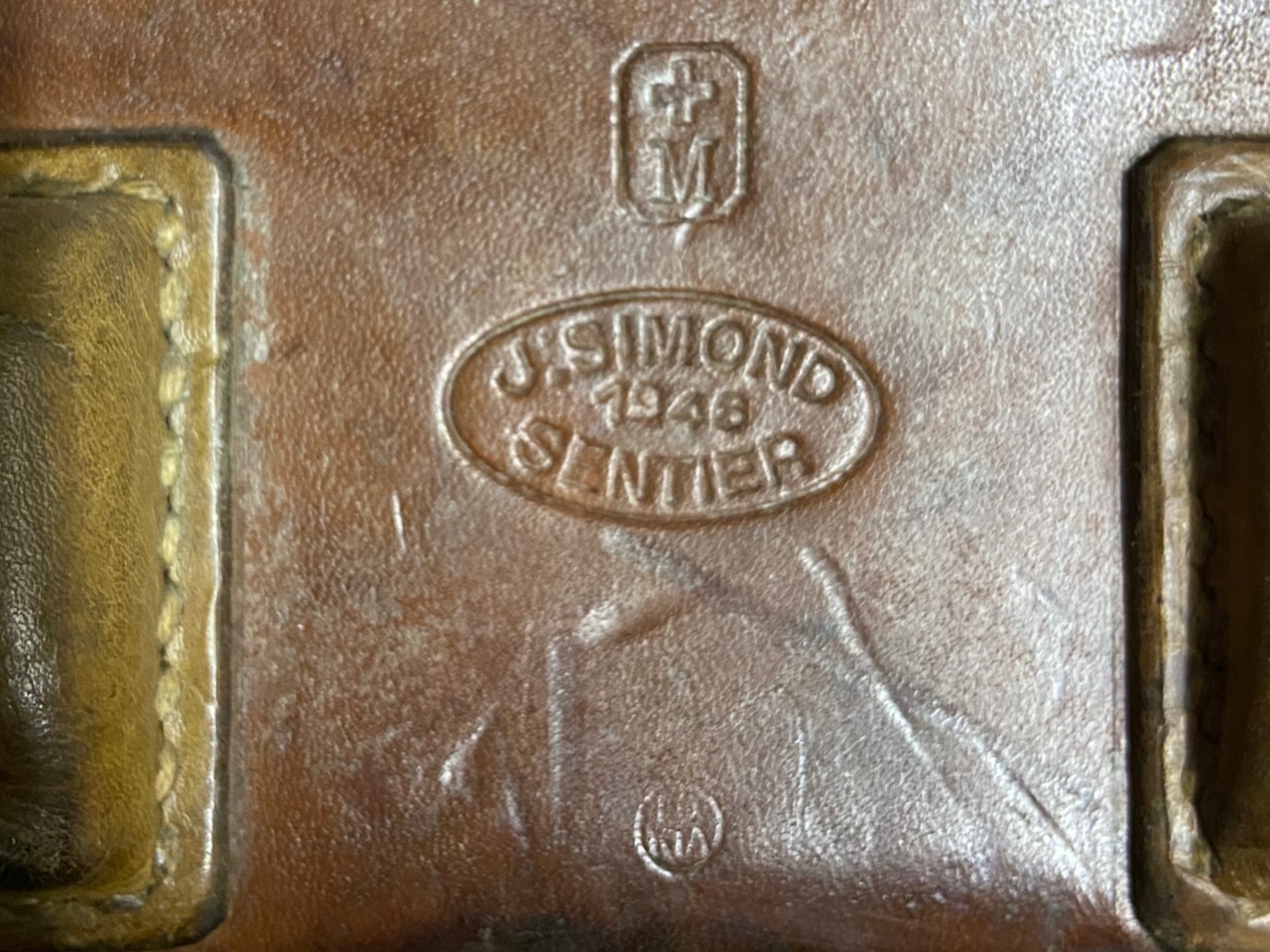
Knapsack 1946, made by J. Simond from Le Sentier.
Here also a second acceptance marks, probably "KTA" (Kriegstechnische Abteilung).
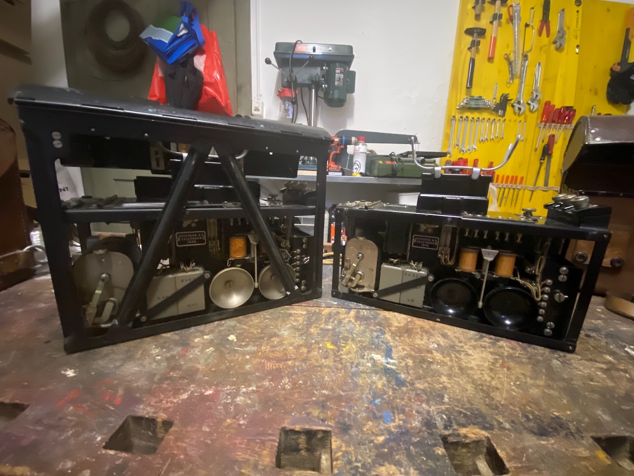
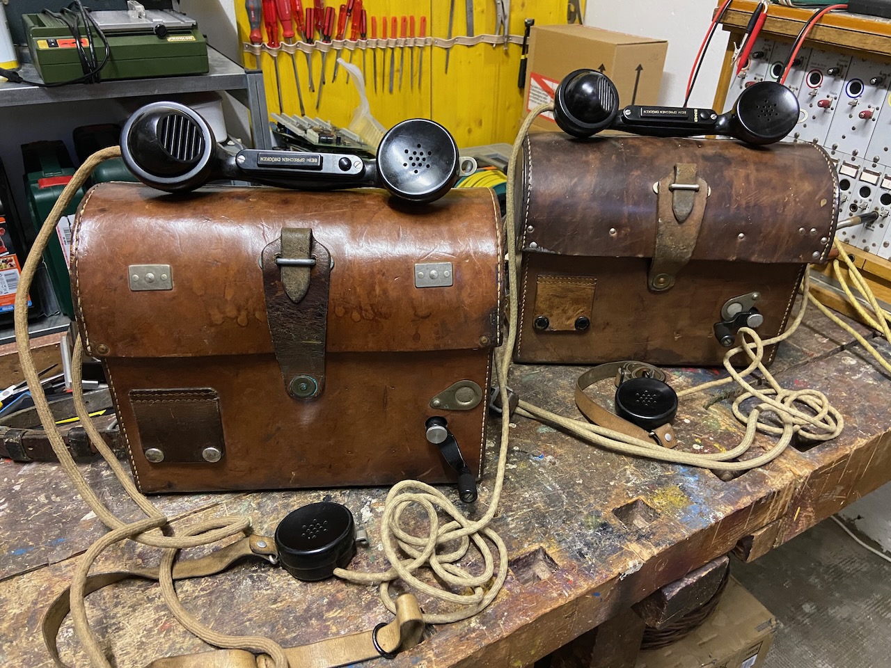
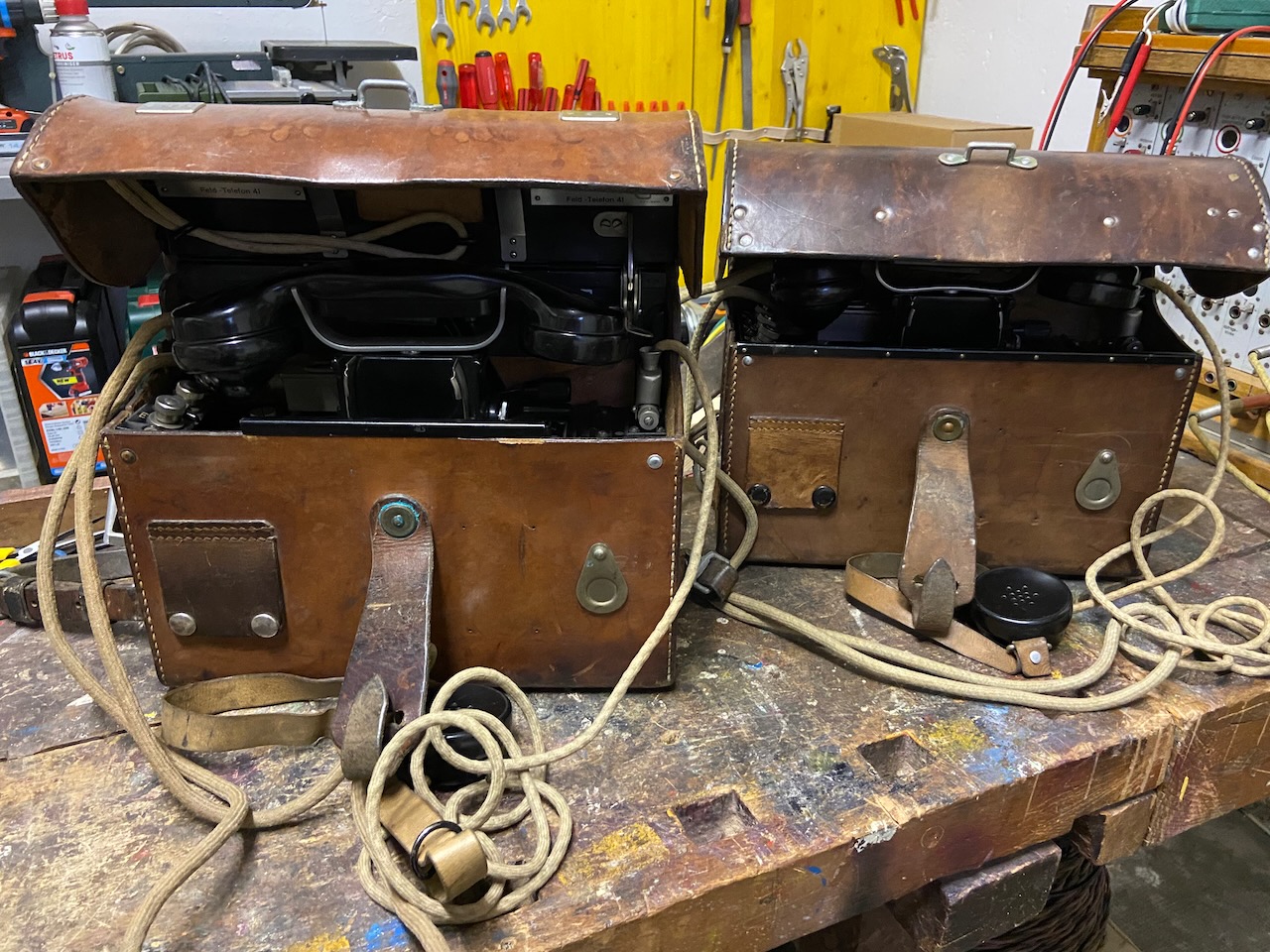
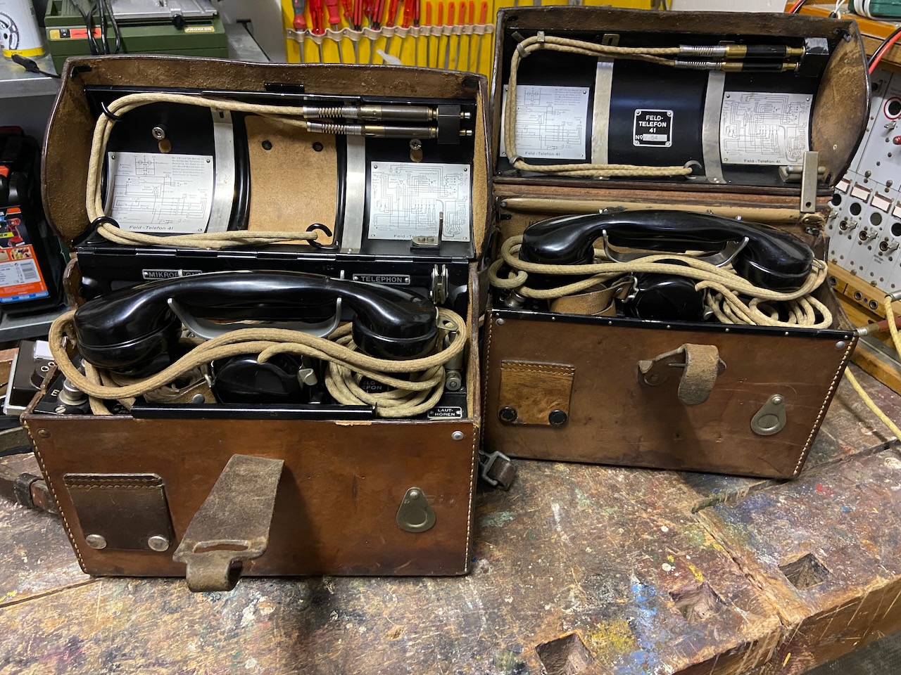
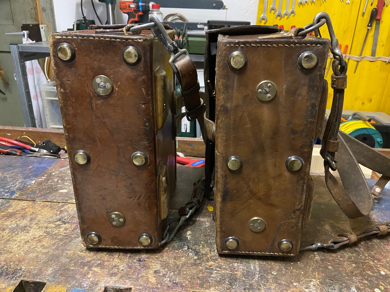
Both series side by side.
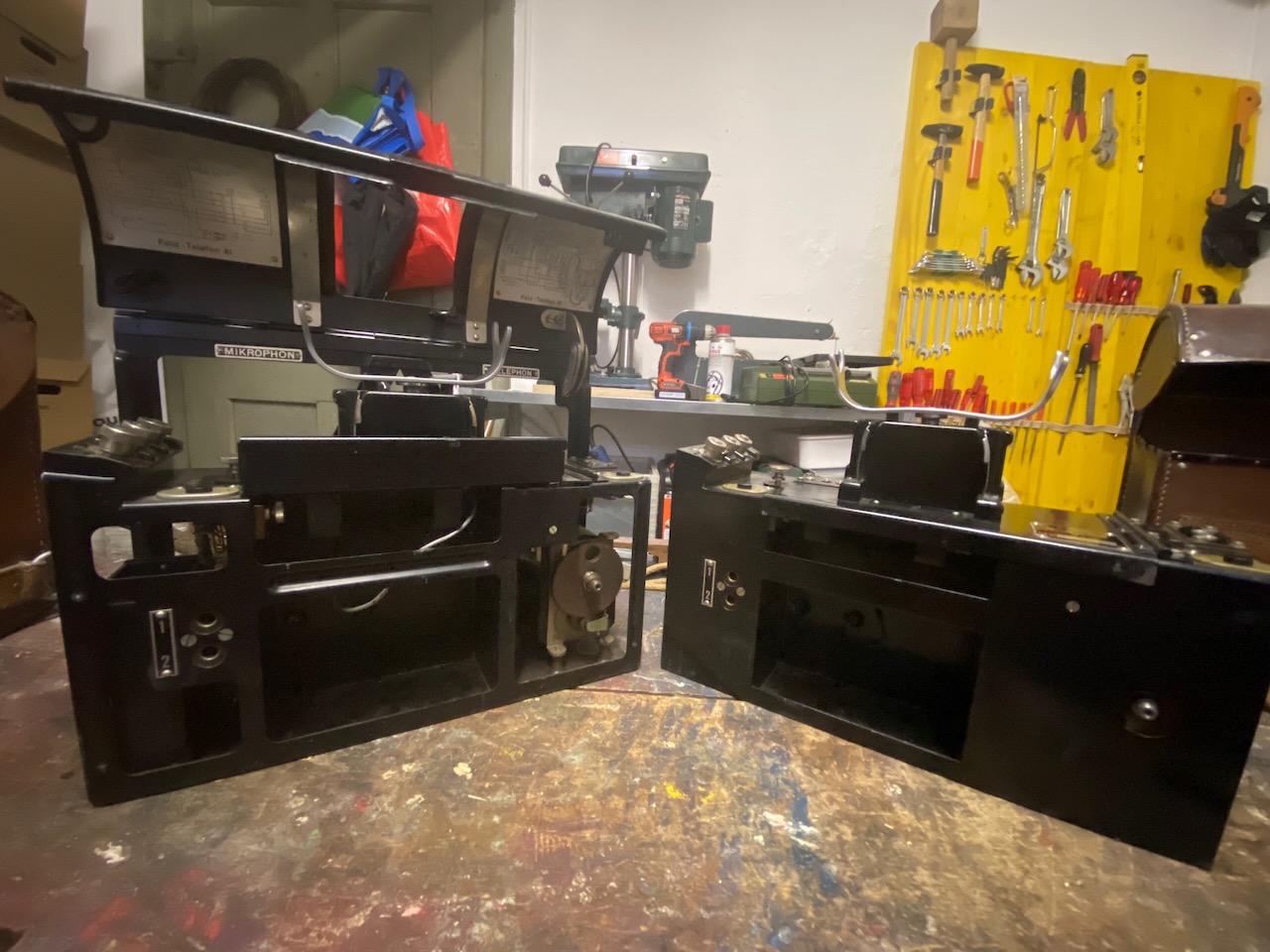
Both series side by side.
Ready for LB use.
Ready for CB use.
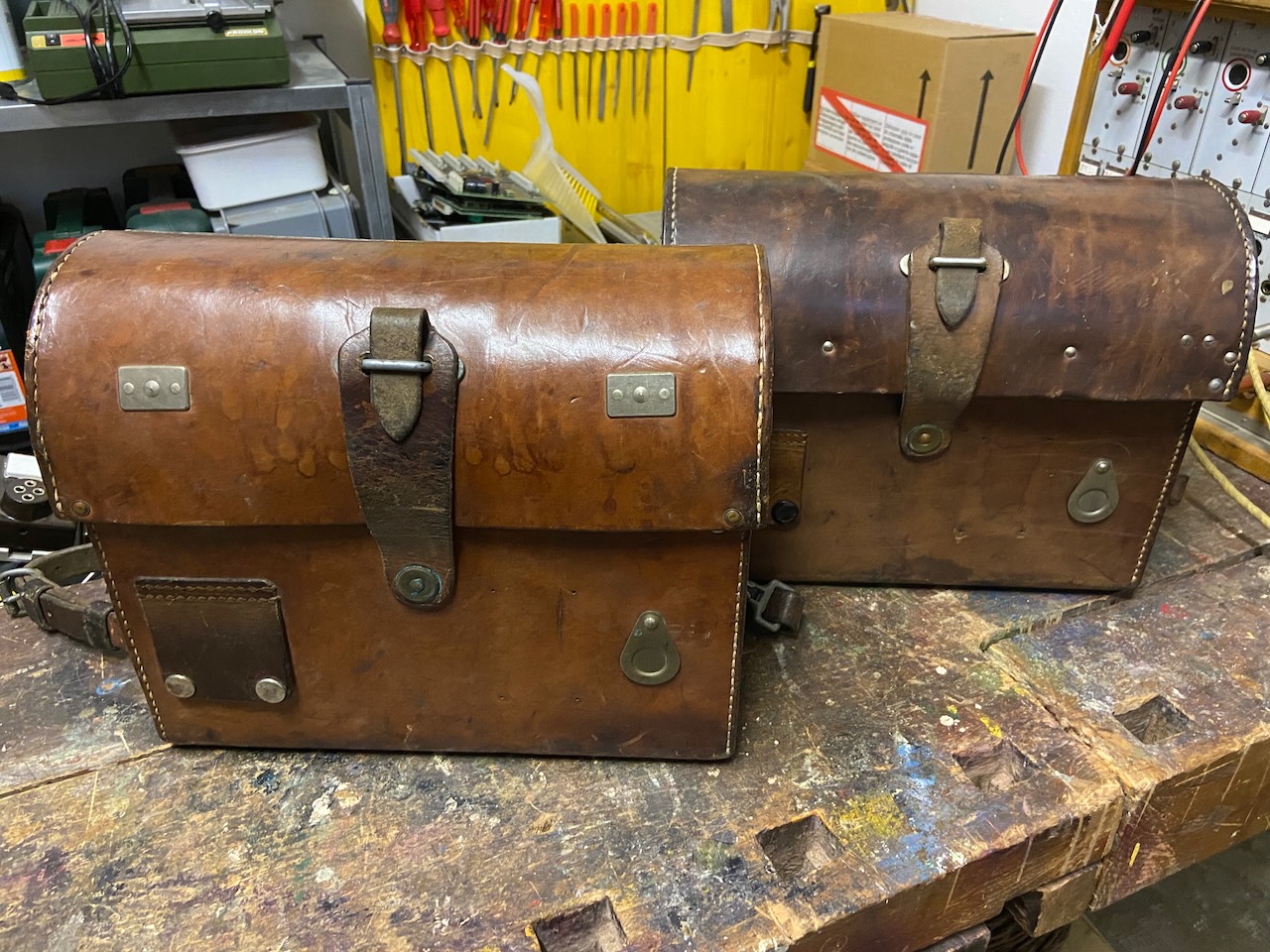
Ready for packing.
Ready for transport.
Carrying straps.
Fix at the top, removable at the bottom
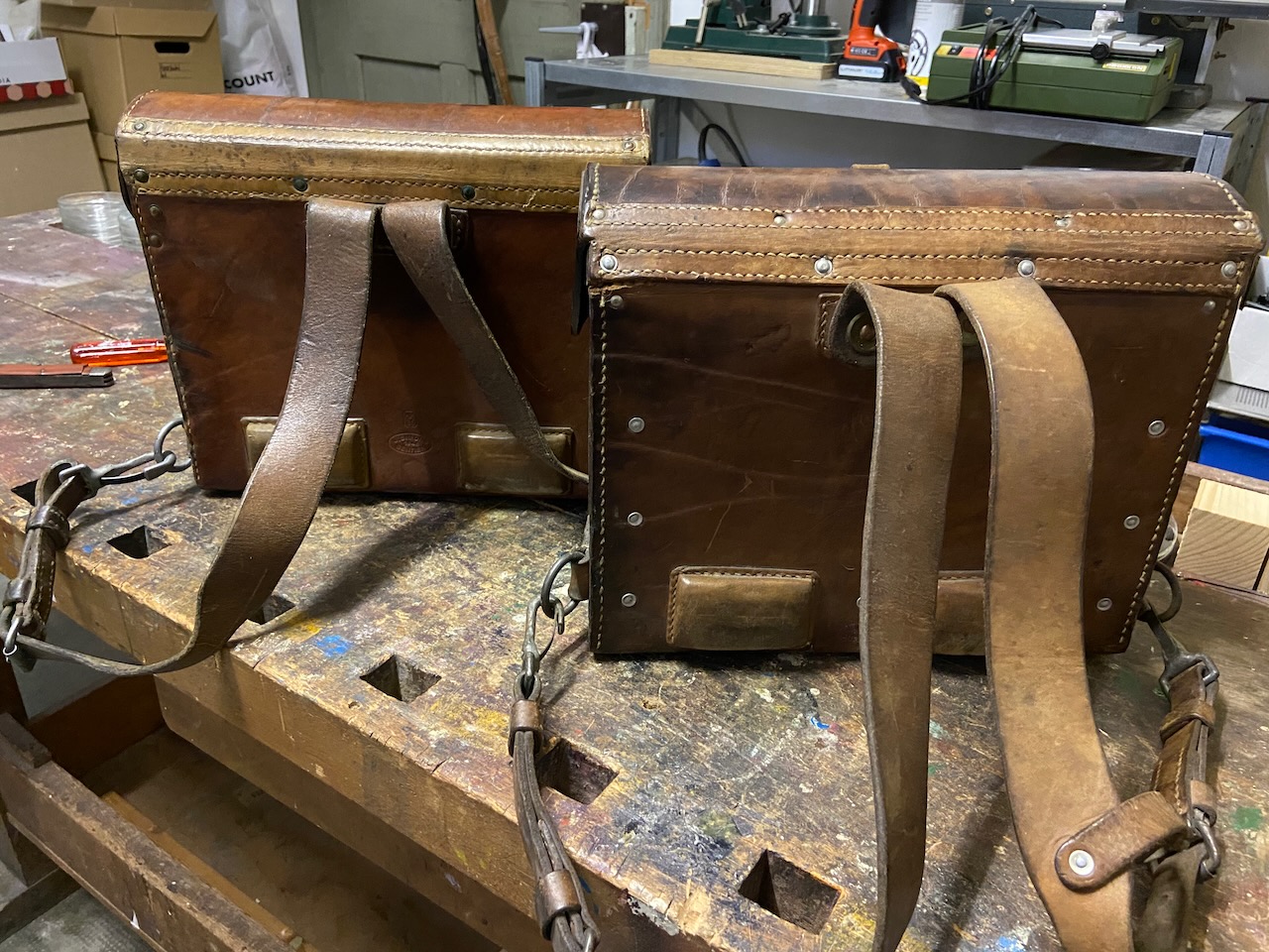
Captive screws which hold the body and metal feet on the bottom
The serial/ID number is also marked on the knapsack.
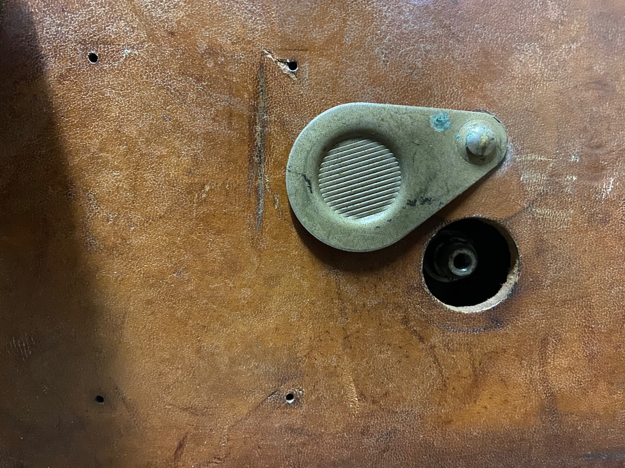
The magneto hole is covered by a small metallic latch.
Left of that the spelling table was mounted (these were removed in the late 40ies when a new spelling table was adopted.)
The patch sockets are covered by a leather latch.
Socket 1: Telephone.
Socket 2: Line.
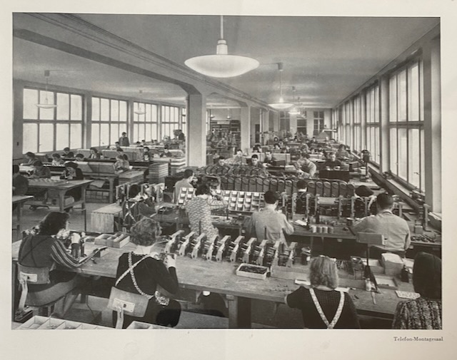
View of the Autophon telephone manufacturing floor in 1942 [5].
It is hard to tell whats mounted on certain tables, but you can see the leather boxes of the "Feldtelefon Modell 1941" on the third row table.
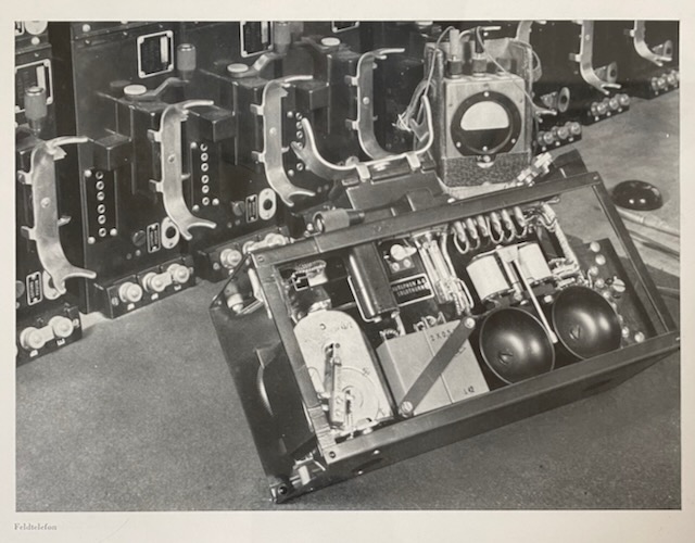
Lot of devices in the Autophon factory (probably at the test station) [5].
Creative Commons Attribution-ShareAlike 4.0 International License