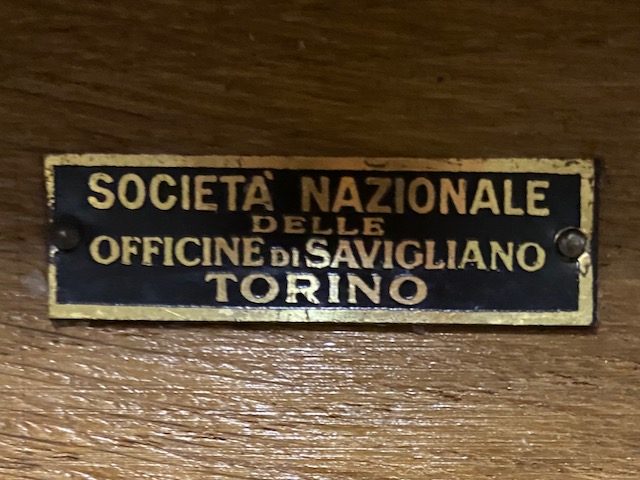
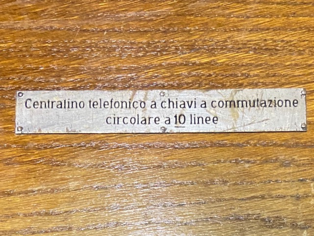
The "Centralino telefonico a chiavi a commutazione circolare a 10 linee" (10 line circular key telephone switchboard) is an italian switchboard from 1926 using an interesting setup: circular switches instead of cords. There was also a 6 line version and an updated slightly smaller version (6 and 10 lines) of 1932 [1] [3]. This specimen and all others I know off or have seen pictures of are made by Società Nazionale delle Officine di Savigliano (later owned by Fiat, now part of Alstom). This switchboard has also been in use in the Spanish civil war by the Francoists (Gracias for this Info @Cesar).
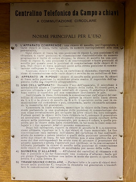
Switchboard description from the user guide attached to the top lid inside (translated from Italian):
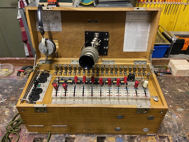
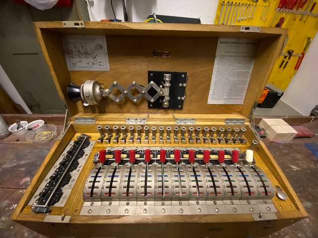
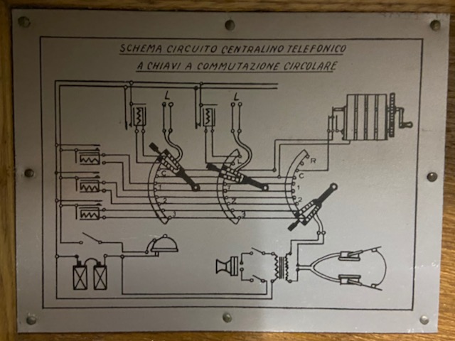
The device includes: a listening key, for the operator, and various line keys, all identical, in a number corresponding to its size. Each line key has an idle position L, a call position C and various switching positions marked by progressive number and line of different color; the listening key has a rest position R, a conversation position C and as many listening positions as there are switching positions of the line keys. Any two Line keys placed in the same switching position connect the respective lines. Each key is served by a call relay flap; each switching position of the various keys is served by an end relay flap.
Typical switchboards of that era were cord-based. This switchboard uses a set of circular switches where each color coded position represents a possible interconnection of two or more lines. From an operator point of view a preferable setup, from a reliability point of view probably not so much, compared to e.g. a single cord 10 line setup with 20 contacts (10x2; for each plug/socket) this setup has 100+ contacts which e.g. can corrode.
Switchboard relay flaps are most often "gravity" based, they fall when released by the relay hook. With this setup the flaps need to be spring loaded to activate. Also not something which increases the device reliability.
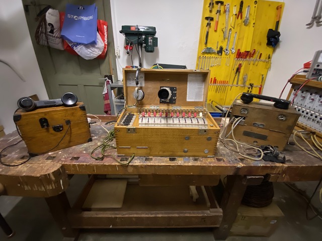
Setup used for the demo in the video.
On the left connected to line 1 a Czech VZ.23, on the right connected to line 2 an Italian GA.31.
In use.
Here lines 3 and 1 are in use and the operator is connected to line 2.
Line 3 has just called of (the green flap is up).
Same from the left.
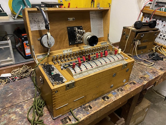
Same from the right.
He the magneto handle is visible, folded out.
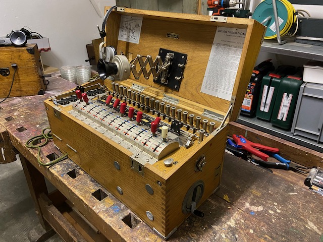
Ready to store.
All switches in base position and the flaps secured by the respective bars.
Ready for transport.
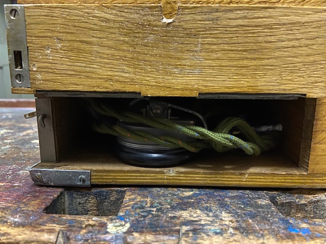
Behind the door on the left bottom the headset is stored.
![]()
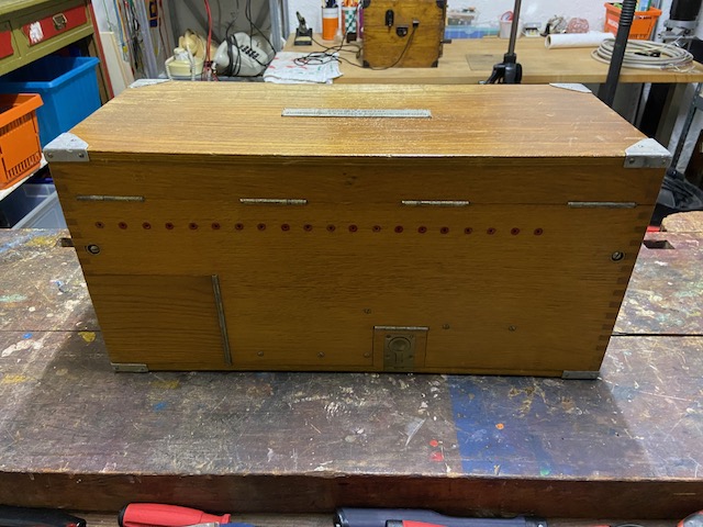
From the back.
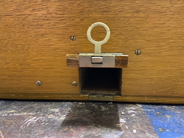
On the left the battery compartment door.
In the middle an additional compartment door with unknown usage (may have contained the earth pike or some cables).
The 20 small holes marked by red circles are the wire inlets.
Headset compartment.
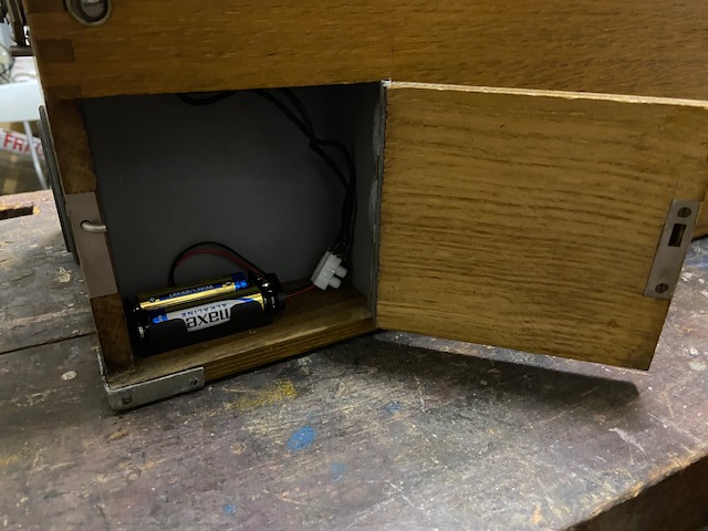
Battery compartment.
(With a modern battery replacement).
Compartment with unknown use.
(Maybe for earth pike)
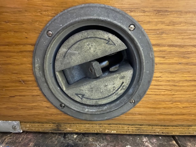
Magneto crank lever (foldable).
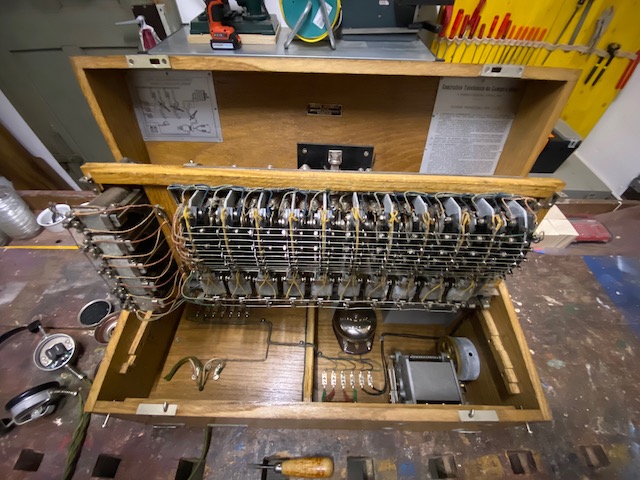
The main board flipped up to reveal the innards.
Magneto and DC-Bell.
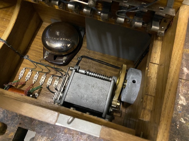
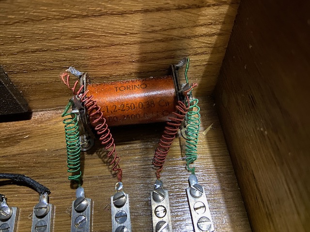
Inductor coil.
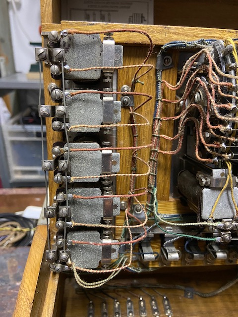
Bottom side of the 5 connection way relays.
The red and yellow wires are the relay connections, the bars on the left are the DC-ring connections.
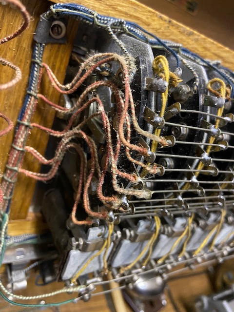
The first circular switch, where we meet the red and yellow wires again.
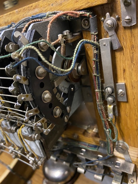
The last corcular switch which is the operator switch.
To the right of it the fins from the ringer on/off switch.
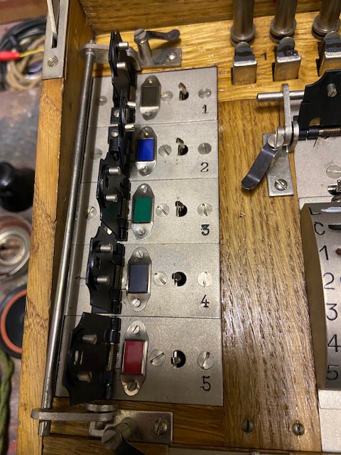
The 5 connection way flaps all up indicating the same color than marked on the circular switches.
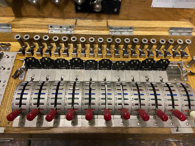
All the line flaps up.
Behind the line flaps the lightning arrestors for each line wire and behind that the line binding posts.
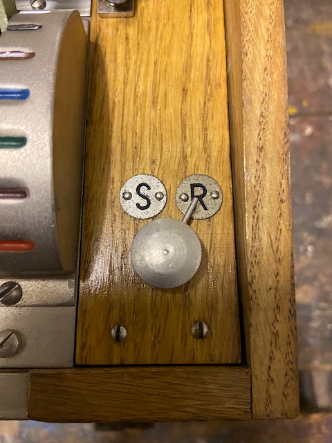
The ringer switch, S=Suonare (=on) R=Riposo (=off).
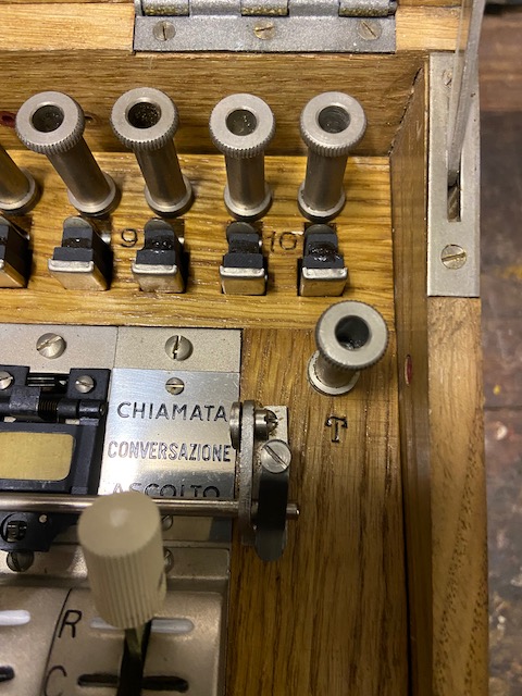
The earth binding post T=Terra.
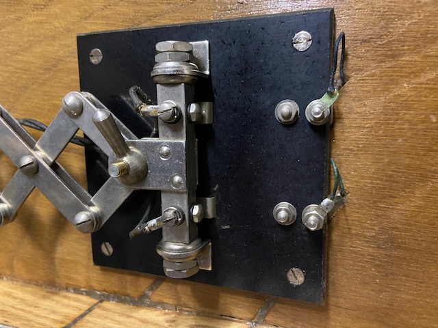
At the back of the microphone arm the contacts connect when the arm is folded out.
When folded back the contacts are open = microphone off = no battery consumed, hence the user guide states: "... but remember, at the end of the service or for long rest intervals, to fold down the microphone against the body so as not to unnecessarily consume the batteries."
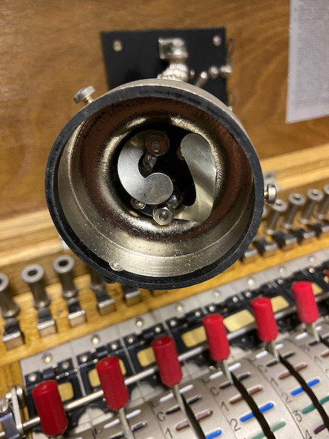
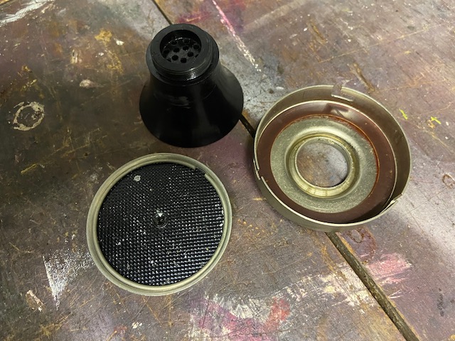
Microphone mouthpiece and capsule removed.
Mouthpiece lid and TX capsule.
User guide inside top lid.
Circuit diagram inside top lid.
Manufacturer label inside top lid.
Descriptive label outside top lid.
Creative Commons Attribution-ShareAlike 4.0 International License