The Austrian field telephone M35 was developed and manufactured by Kapsch & Söhne in Vienna (Kapsch continues to be one of the most important players in todays - 2020 - telecom market in Austria). Only 4800 pcs. were delivered between 1935 and 1938. The instrument has strong similarities to the Norwegian Modell 1930 made by Elektrisk Bureau and the Italian G.A. Mod. 1931. Between the Norwegian and Italian models it is not clear who was first but both were earlier than the M35. Perhaps Kapsch licensed the Design. For sure the Kapsch engineers designing the Instrument had seen either or both of the aforementioned instruments. Feature and build quality-wise the M35 surpasses the Norwegian and the Italian versions.
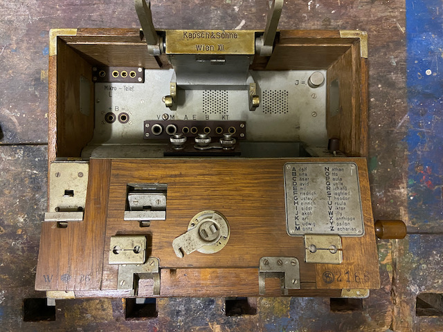
The M35 supports LB and CB operation. It features sockets for an additional headset, patch sockets for line and instrument connection, and a mounting option compatible with the german type FF26 dial box ("Nummernscheibenkästchen"). The front door provides small lids to pass line, handset and patchcables through. The hook switch folds out by using an expensively built spring loaded "push sideways to unlock" mechanism. According to indication on the diagram there must have existed an external lightning arrestor box which can be connected to special sockets. The ground spike is mounted to the front lid inside.
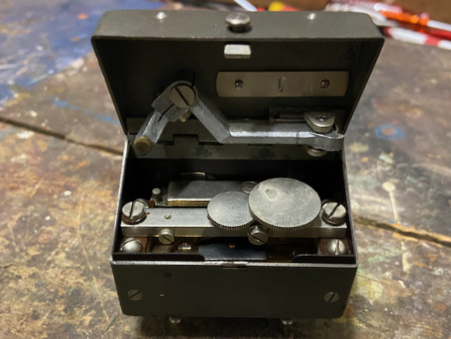
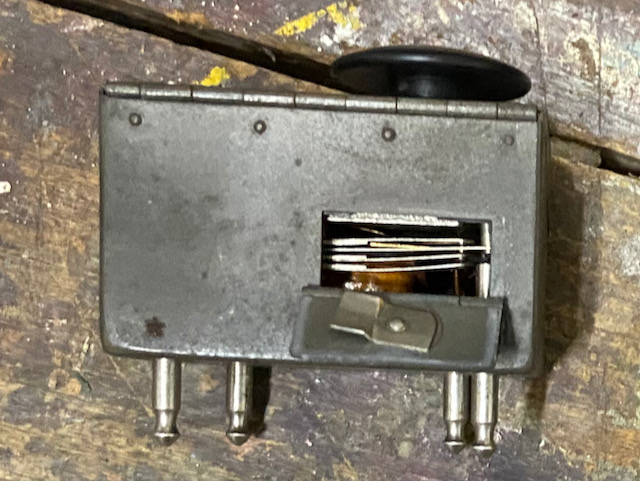
The buzzer is modular and can be taken out of the instrument to adjust or replace. On the back of the buzzer a small door allows to access the contacts for cleaning. When the buzzer is removed the instrument can not work as the transmitter circuit is interrupted. The buzzer can only be operated with the instrument front door open. All in all not a very practical buzzer design.
A completely unique feature found on no other field telephone is the option to switch the generator to be used as a DC generator to provide emergency power to the transmitter in case of battery depletion.
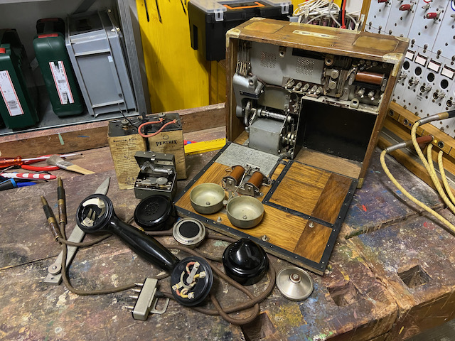
Disassembled.
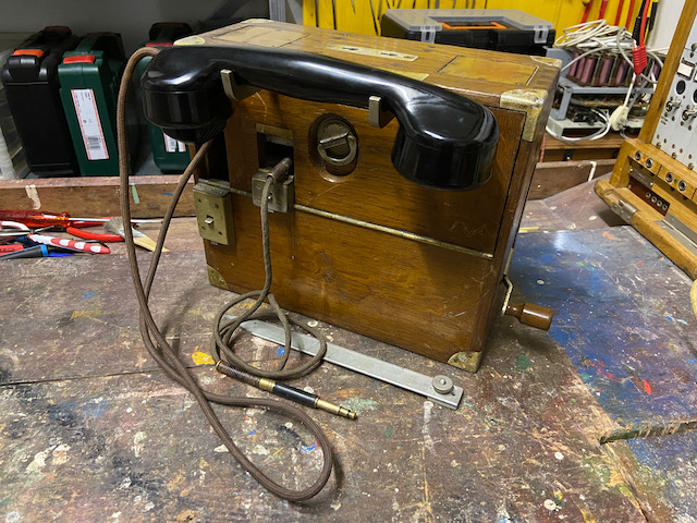
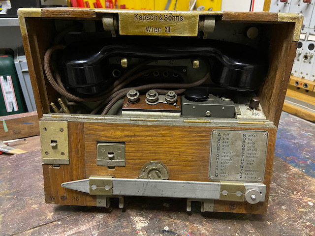
Ready to use.
Lids for line and handset and patchcord open.
Generator handle folded out.
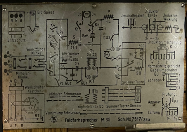
The diagram hints at an external and optional "Blitzschutz" (lightning arrestor) and "Wahlscheibenkästchen" (Dial box).
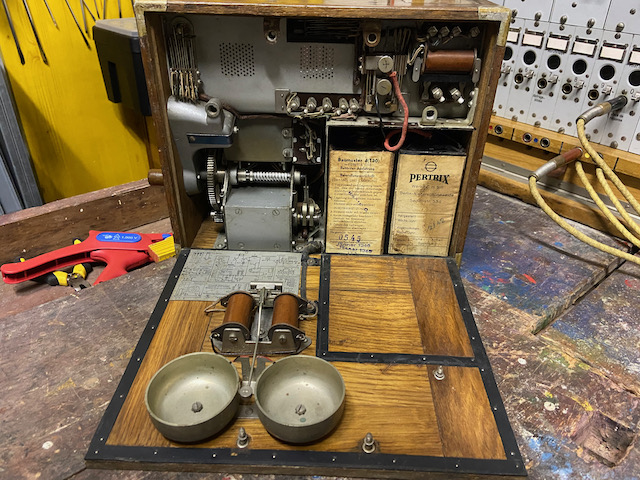
Behind the back door the generator, capacitor and coil.
The battery compartment holds two size 4 1,5V elements.
The ringer and diagram are mounted to the back door.
On the front inside top left the handset socket.
In the middle the folded out hook switch and on the right the knob to switch the generator (J for Induktor) from AC to DC.
There is a socket for an external battery connection, then the V socket (Vermittlungsklinke) to connect the line to another instrument or the M socket (Mithorchklinke) to connect the instrument to another line.
The "A E B" socket is for an external lightning arrestor connection and the KT (Kopftelephon) for an additional receiver.
Inside the lid the year of make (36) and the serial no. (2166) and also a spelling alphabet.
The buzzer with open top lid revealing the two regulating screws.
The buzzer is connected to the instrument by 4 plugs.
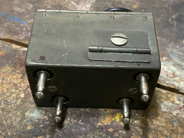
The buzzer backdoor provides access to the contacts for inspection and cleaning.
The bakelite handset is very similar to Austrian PTT type 1931 handsets (most probably also made by Kapsch).
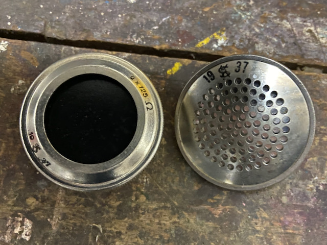
The TX and RX elements are replaceable.
The handset cord ends in a 4 prong plug to connect to the instrument.
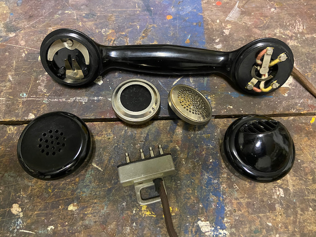
The RX and TX elements also made by Kapsch, year of make 1937.
The hook switch cradle folded in and the handset stored.
The earth connector provides a moveable latch to leave either open or to shorten E with line connectors A or B.
The buzzer is operated using the big black knob, by moving the small knob on the right to the left the buzzer can be blocked.
The lever switch on the far right can be used to either test the instrument (front position) or the line (back position) using the generator and the ringer.
On the left there is a compartment to store tools and e.g. the patchcord.
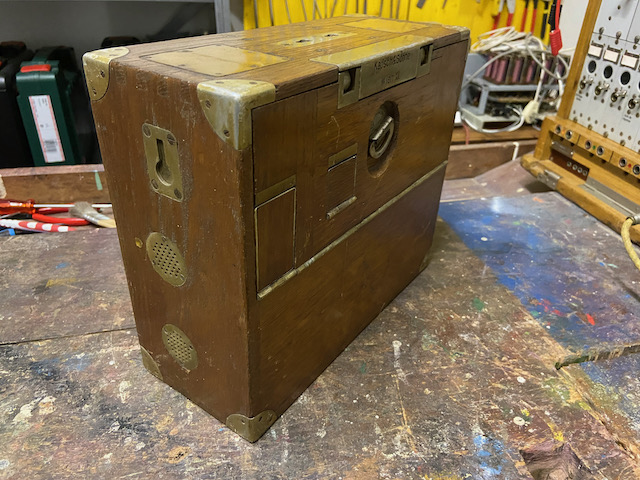
Front door closed.
![]()
Generator handle folded in.
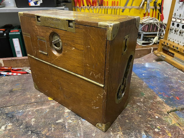
On the left side perforated lids to allow air circulation to the battery compartment.
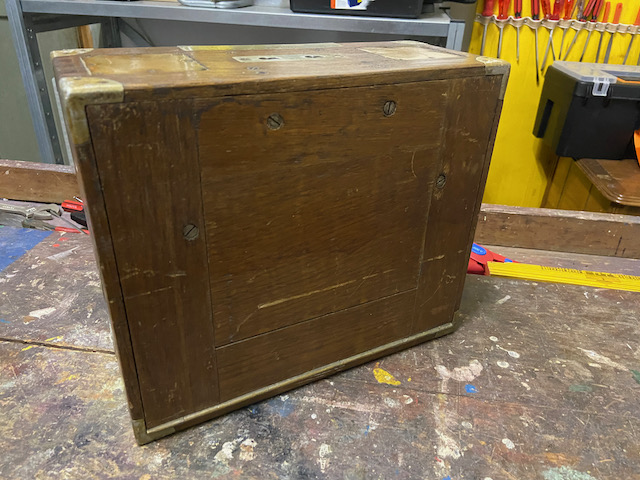
The back door closed, held with 4 captive screws.
Creative Commons Attribution-ShareAlike 4.0 International License