Find more details on Swiss field telephone history on the Swiss Army Field Telephones Timeline.
The Swiss Army field phone Central Telephon (C.Tf., Models: 1913, 1918 Siemens&Halske - 1925 Hasler) was first introduced in 1913. This Model is from after 1918. Originally designed and built by Siemens & Halske, Berlin the Central Telephon was later refurbished and modernised in Switzerland by Telefonwerke Albisrieden (The Swiss Siemens subsidiary) and Hasler. Hasler delivered also a locally built Central Telephon Modell 1925. Between the Models 1913, 1918 and 1925 there were about 900 pieces of the C.Tf.
In the 1920ies most of the older instruments were refurbished with better buzzers ("Albis Summer" from Telefonwerke Albisrieden or "Englischer summer" from Hasler). In 1935 all instruments were again refurbished with new types of rx and tx elements, the capacitors were replaced and new inert gas lightning arrestors were added.
The C.Tf. is still mentioned in the regulations of 1941. During WWII the instruments were retired and then liquidated in 1956.
Description from "Vorschriften für den Telefon- und optischen Signaldienst der Artillerie, 1941" (Translated and slightly abridged):
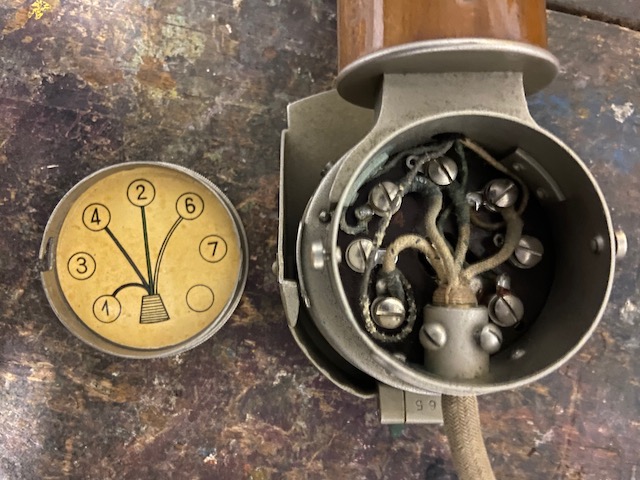
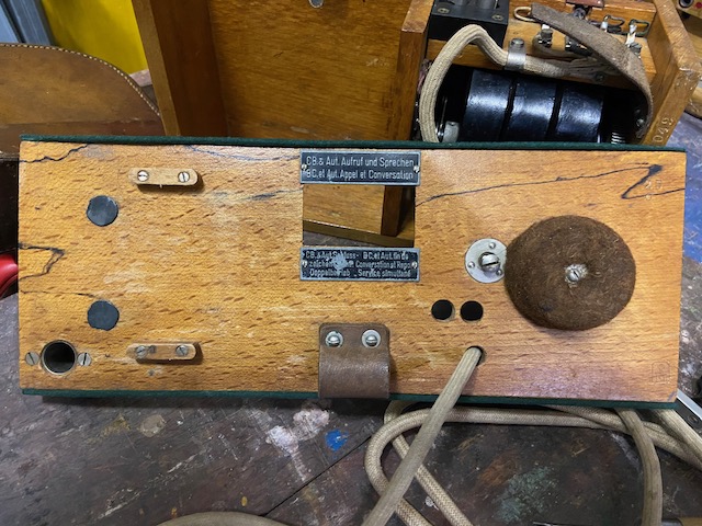
The central telephone (C.Tf.) is built into a wooden box with a carrying strap. The headphone with connection cord is supplied in a special leather case. The black resting socket, a connecting socket labeled 1 and a connecting socket labeled 2 are attached to the outer front wall. When the patchcord in inserted into socket (2) the device is switched off, while it is switched on when using socket (1). The fold-out buzzer button and the loudspeaker button as well as the insert point for the inductor crank, which is covered by a lid, are located on the right side of the box. The inductor crank is supplied inside the box, along with a screwdriver. The exact circuit diagram of the C.Tf. is attached to the inside of the box lid. The handset with connecting cord lies on the insert box. It corresponds to that of the Art. Tf. with the difference that it has no buzzer button. The switch with the contact points for dual operation and central battery call should be set as follows:After loosening the cover screw, the bottom screw and the red and black connecting wire on the terminals, the insert box can be pulled out. Now more parts are visible:
- For operation on field telephone lines (i.e. for use in the artillery): Always set the lever to the "Aufruf und Sprechen“ contact.
- To call up and while speaking with a central battery station: Move the lever to „Aufruf und Sprechen“.
- In the case of dual operation (simultaneous telephoning and telegraphing on the same wire) and if there is no speaking: Set the lever to „Doppelbetrieb“.
- When C.Tf. at the same time to an F.Tf. is connected: Set the lever to "„Doppelbetrieb“".
The capacitors enable the connection of the C.Tf. on lines with dual operation and central battery operation. The overvoltage fuses are located on the inner side compartment of the box and cannot be removed with the insert box.
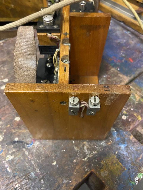
- The battery is built in the same way as with Art.Tf. and has two connection terminals marked + and - on the long wall of the insert box.
- The crank inductor is on the same side. The jacks for the headphones are attached above this.
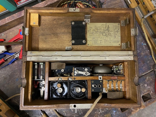
- Ringer, buzzer, induction coil, two capacitors, buzzer button and contact spring for the loudspeaker button are located on the other side of the long wall.
From point of view of the until then in the Swiss Army used Feldtelefon (1909) and Artillerietelefon (1915) which were built for buzzer only operation the Central Telefon introduced the magneto and AC ringer.
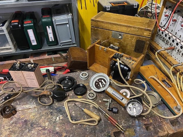
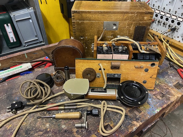
Disassembled.
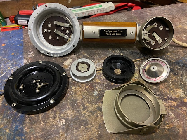
All the parts.
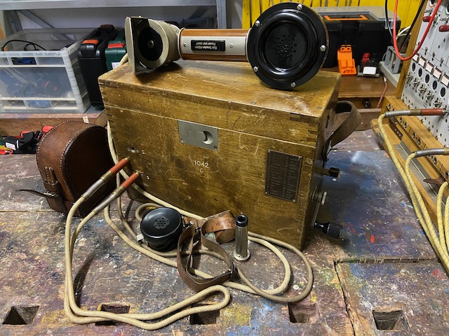
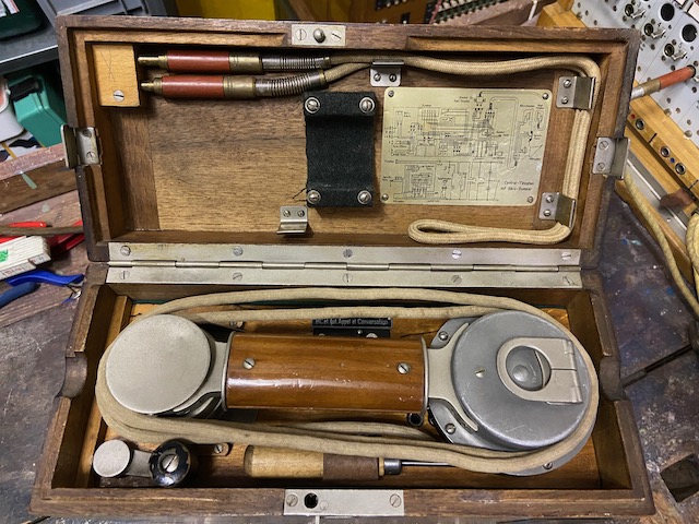
Ready to use.
The magneto handle mounted.
The buzzer lever folded out.
The headset plugged in.
The patchcord ready in socket 1 (Mithör-Klinke, instrument connected) and blind socket.
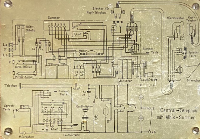
Wiring and electrical diagram.
The headset open, with the 200 ohm type 1931 rx element.
The handset plug has terminals where wires can be connected directly and as such the headset on its own can be used as emergency or line installation sound powered telephone together with the signalling whistle.
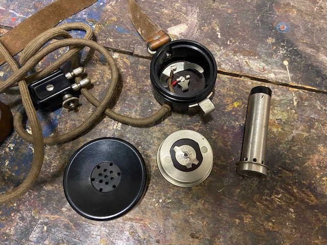
The handset has been refurbished and modernised in 1935 to use RX elements of Swiss PTT type 1931 and Siemens & Halske TX Elements type 1928.
The RX element is hold in position by a recess in the bakelite cover (not visible here).
The handset is connected by a four wire cable.
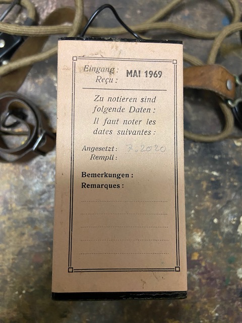
The instrument uses 2x 1,5V elements of size 4.
This Lagerelements are made by Leclanché, a Swiss battery factory, for the Swiss Army (produced until at least the 1980ies).
The elements are of inert type and have to be activated with adding water.
The should be used 10 to 12 hours after activation, or in emergencies already after 2 hours.
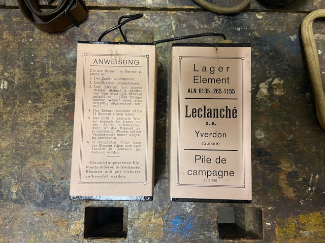
This element was manufactured in 1969 and activated more than 50 years later, it works perfectly.
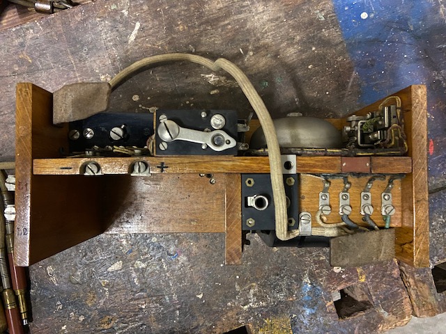
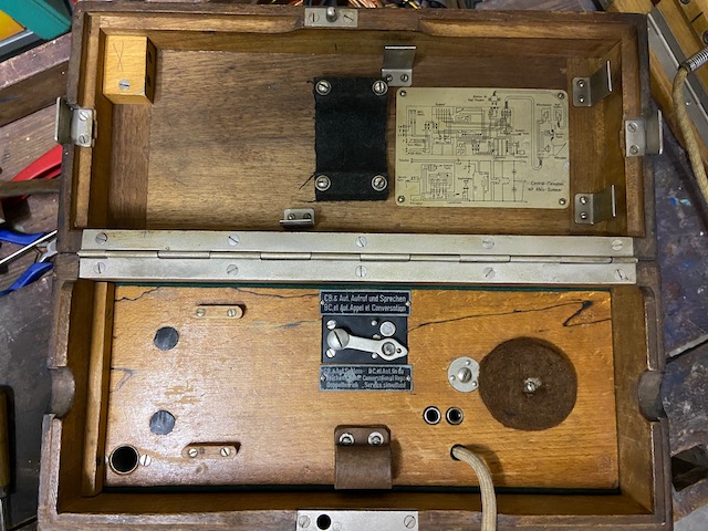
The dismounted body lid.
Openings for the LB/CB switch and the headset connectors.
Socket to store the magneto handle and a lug to store the screwdriver.
The headset RX side is rested on the felt.
The Line connectors on the body which connect to the assembly in the main box.
On the left the battery compartment.
On the right above the magneto the headset socket and the handset cable connection.
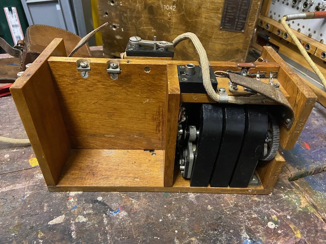
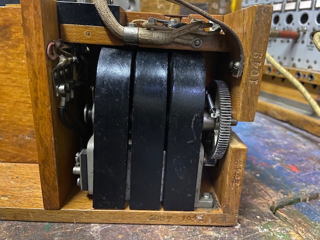
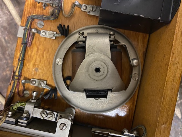
The magneto.
The device serial number 1089 has been striked through and replaced by 1042 (which corresponds to the number on the box), probably changed during refurbishment in 1935.
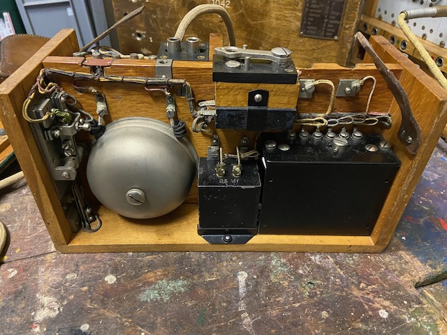
Body top.
The handset connections are color coded.
On the left the buzzer switch and below the volume increase switch (shorten out the induction coil).
The single bell ringer.
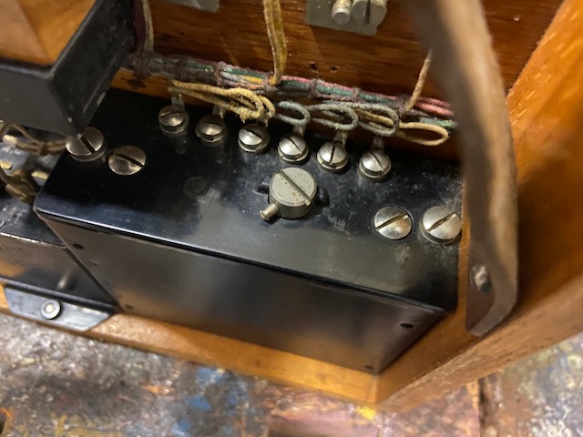
The capacitor box.
On the right the sealed Albis-Summer (buzzer).
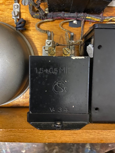
The 1,5 and 0,5 uF Capacitor block replaced when refurbished in 1935.
The sealed Albis-Summer (buzzer), buzzer and induction coil circuits combined.
Can be regulated by screw in middle.
The ringer without bell.
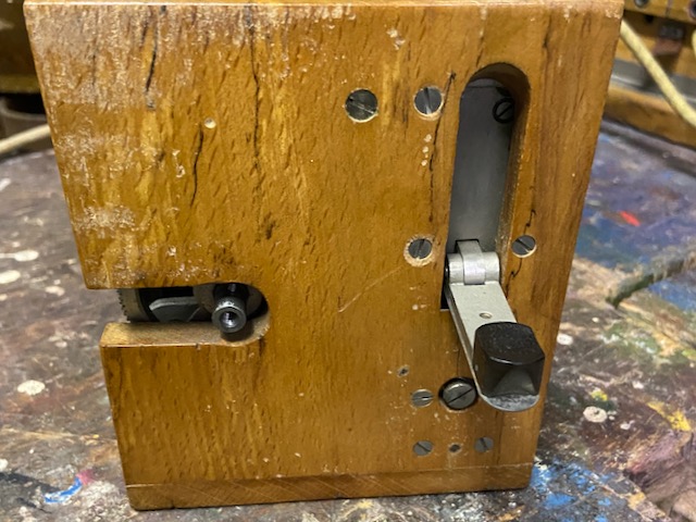
On the right side the magneto opening, the buzzer fold out lever and below the volume increase button (shorten out the induction coil).
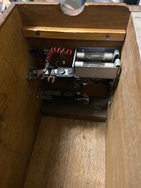
The line assembly in the box including the patchcord sockets and the lightning arrestors.
The black and blue cable connect to the body.
The body mounted in the box with batteries.
The lid closed.
Handset, patchcord, magneto lever and screwdriver stored.
Box front.
The serial number 1042 and the instrument type C for Central Telephon.
On the left the patchcord socket 1 (Mithör-Klinke, instrument and line connected) and 2 (Anschluss-Klinke, line connected, instrument disconnected) and the blind socket to store the patchcord (When stored the patchcord should be plugged into 1 and the blind socket).
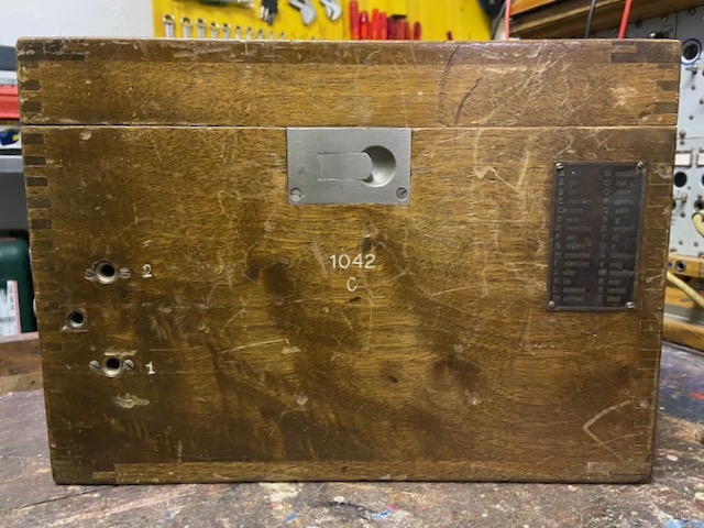
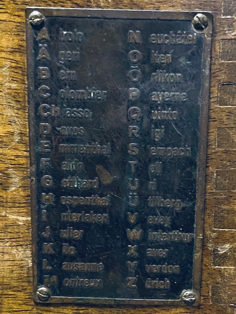
The spelling alphabet.
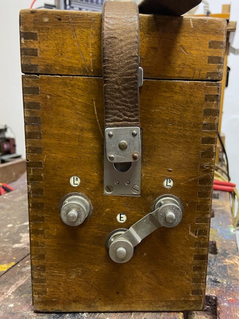
Line and earth connectors.
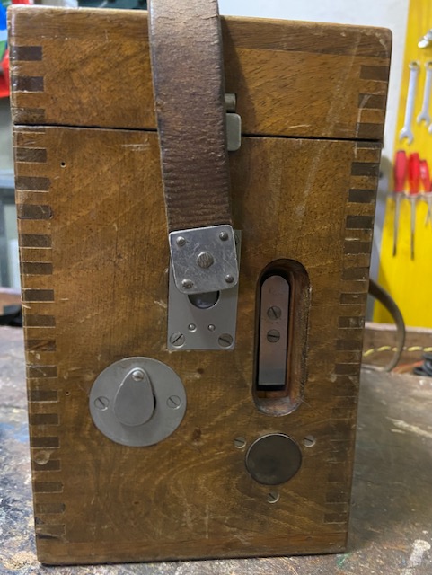
On the right side the magneto opening with lid, the buzzer fold out lever and below the volume increase button (shorten out the induction coil)..
Ready for transport.
![]()
Creative Commons Attribution-ShareAlike 4.0 International License