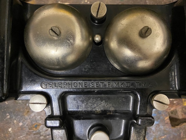
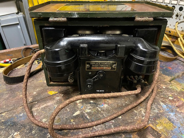
The British field telephone set F. Mk. II. is an updated version of F. Mk. I. The main difference i can identify is that Mk. I. used a cast-alloy body whereas the Mk. II. has a bakelite body. I have yet to find historical documentation regarding this instrument. I assume that Mk. I. was developed and introduced in the 30ies (The Mk. I. manual which can be found online is dated 1939) and Mk. II. was introduced in ~1940 (The here presented model has shows a manufacturing date of 1940 on the magneto). This instrument was made by T.M.C. (Telephone Manufacturing Company Ltd. London). Based on the batteries found the device presented here are from 1979 it can be assumed that this models were still in use up to the eighties.
The device ins transported in a wooden box, where it is slid in on felt guides and can be slid out halfway for use, or slid out completely for battery replacement or repair. The body lid is fixed with three screws with big heads which allows to open them manually. Beneath the lid you have access to the batteries and all the instruments parts.
The battery elements used are British type S or X (The batteries found in this device are from 1979 type No. 12). Two of these 1,5V are mounted in series. The set has a hook switch which connects the battery and also puts the holding coil into the circuit in case of CB operations. So the handset Tele Hand No. 5 on this instrument does not need a P.T.T. switch. The RX element used is a dynamic type, expected to be more efficient thant the classic RX setup. It is also well suited to be used as emergency sound powered TX element in case you run out of batteries.
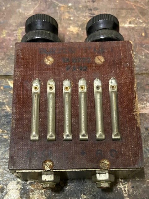
Pluggable buzzer Module (Buzzer T.Mk.I.). The buzzer module can be replaced without tools. It seems that on sets which were still used after WWII the buzzer modules were replaced with an induction coil module.
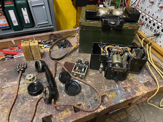
Disassembled.
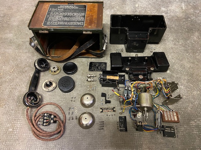
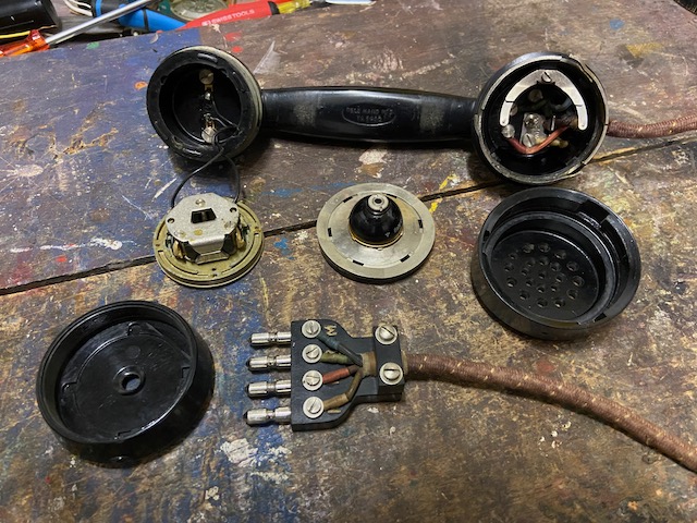
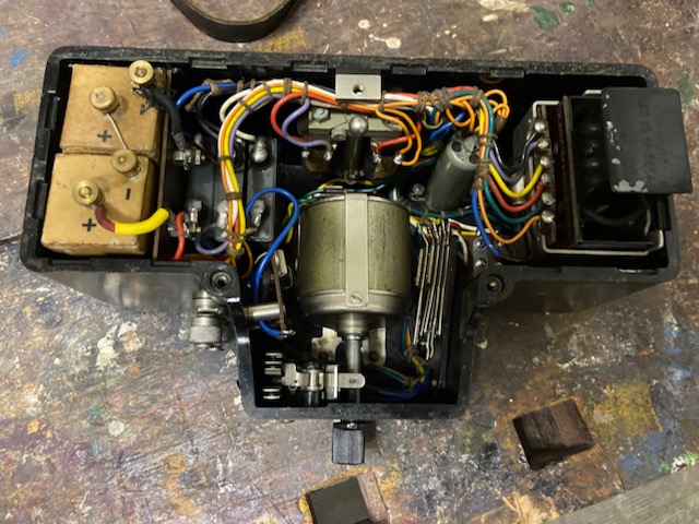
Completely disassembled for thorough cleaning.
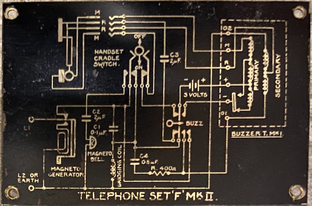
Electrical diagram (Mounted below bakelite top lid).
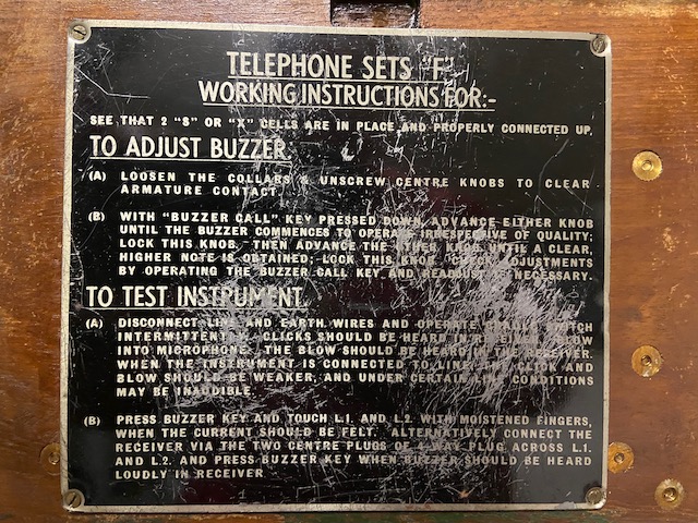
The user guide mounted inside the wooden box lid explains buzzer adjustment and how to test the set.
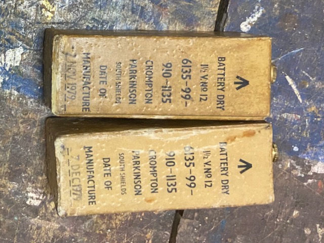
Batteries, 2x 1,5V No. 12 from 1979.
Telephones Hand No. 5.
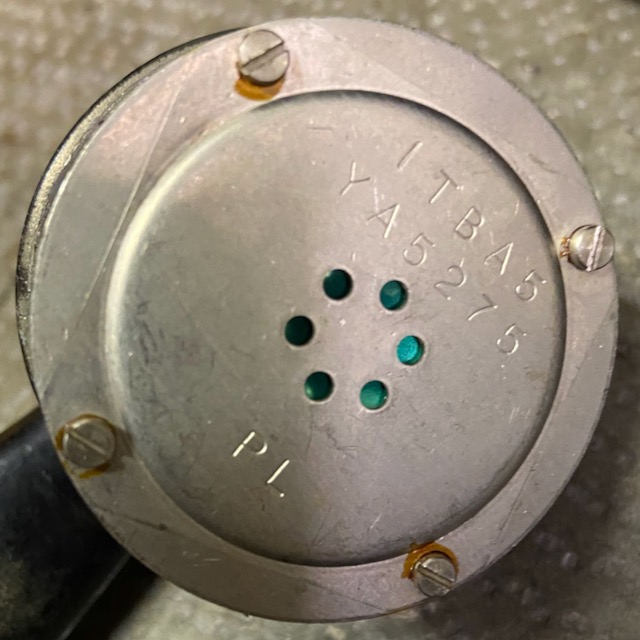
Dynamic RX element.
Ericsson type connector also used on other British field telephones like e.g. the D.Mk.V. (Or the Italien refurbished Version D.Mk.VI.).
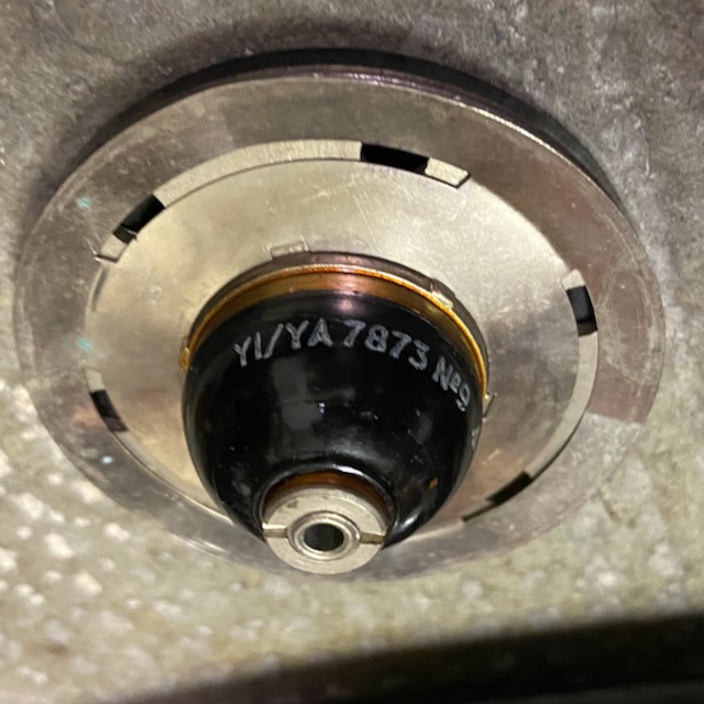
TX element, YI/YA 7873 No 9.
RX element, ITBA5 YA 5275.
The bakelite body from above.
Three screws with big heads to open the lid manually.
The bells are mounted directly to the lid.
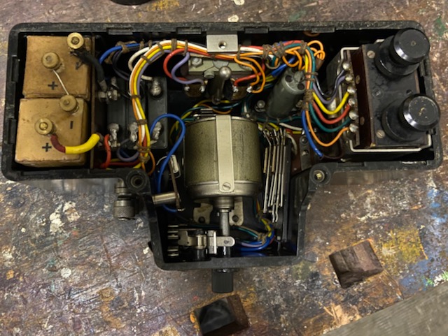
The open body from above.
Batteries, three capacitors, ringer, generator, holding coil, buzzer.
The buzzer open.

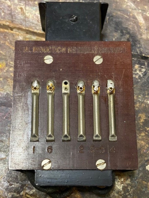
The back of the buzzer with its six contacts.
Instead of the buzzer also a simple induction coil can be inserted.
The coil with a primary and two secondary windings for an anti-sidetone setup.
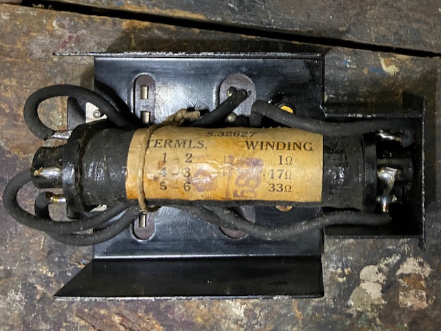
Coil Induction No. 2.
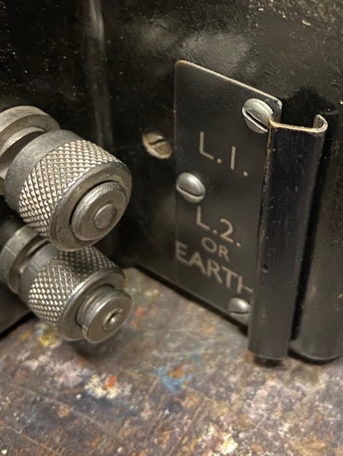
The line connectors on the left.
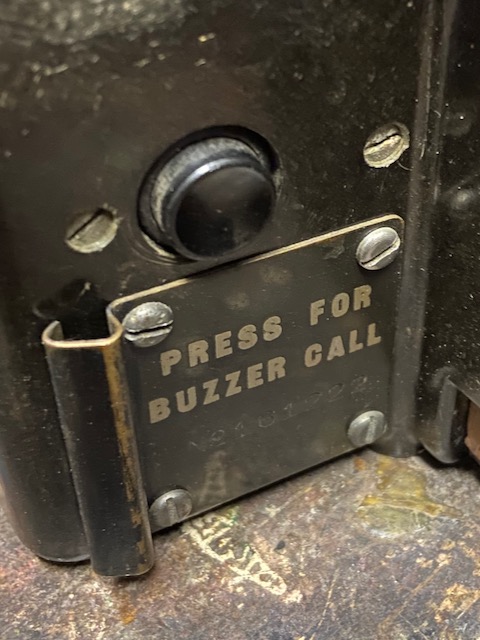
Buzzer button on the right.
The empty wood box.
At the bottom rails and the locking tab.
On the sides and top felt inserts that the body slides better inside the box.
![]()
Ready to use.
Body and handset stored.
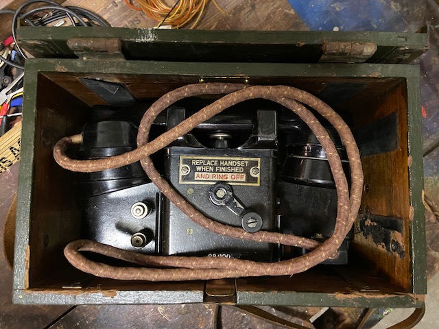
Ready for transport or storage.
![]()
Creative Commons Attribution-ShareAlike 4.0 International License